Disassembly Report: ENPHASE ENERGY IQ8X Micro Inverter
Time: Oct 26, 2023Views:
Introduction
This disassembly focuses on the ENPHASE ENERGY microinverter, specifically the IQ8X-BAT-US model, designed for use in the ENPHASE Encharge 10 battery system. The IQ8X supports both grid-tied and off-grid operations, allowing it to provide power during blackouts, thereby offering a high-quality and flexible energy storage solution. This feature significantly reduces the barrier to entry for users.
The Encharge 10 battery system incorporates 12 IQ8X inverters, with each individual inverter providing a maximum output power of 320W. It operates with a maximum input voltage of 79.5V and utilizes a 21S lithium iron phosphate battery configuration. Additionally, it supports mobile app monitoring and control. In this disassembly, we will explore the internal design and components of the IQ8X microinverter.
Previously, Charging Head Network conducted a disassembly of the ENPHASE ENERGY IQ7+ microinverter, which you can refer to for more information.
ENPHASE IQ8X Micro Inverter Exterior
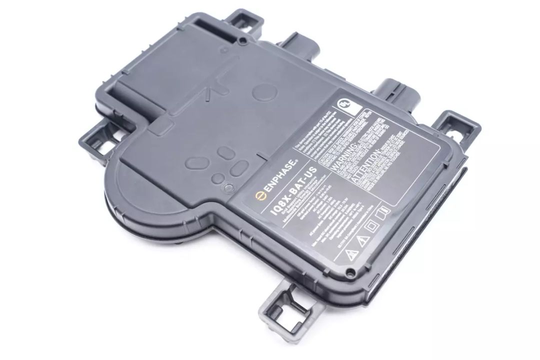
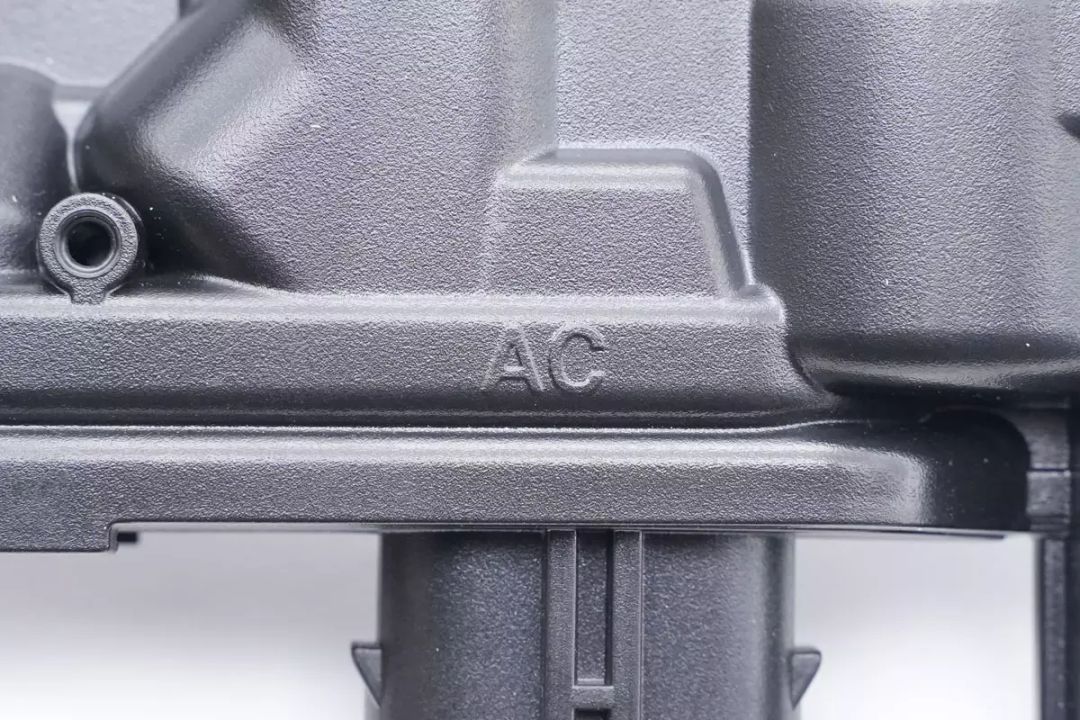
The overall appearance of the ENPHASE IQ8X microinverter is similar to the previously disassembled IQ7+. It features a housing made of PPE+PS plastic, giving it an industrial aesthetic.
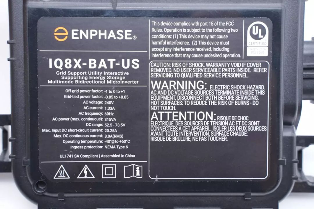
The front of the microinverter features a label with the following specifications:
Off-Grid Power Factor: -1 to 0 to +1
Grid-Tied Power Factor: -0.85 to +0.85
AC Voltage: 240V
AC Current: 1.33A
AC Frequency: 60Hz
AC Output Power (Maximum Continuous Output): 315VA
DC Range: 52.5-73.5V
Maximum Input DC Short-Circuit Current: 20.25A
Maximum DC Continuous Current: 8.0A (RMS)
Operating Temperature: -40°C to 60°C
Protection Rating: IP67
The IQ8X microinverter is UL certified.
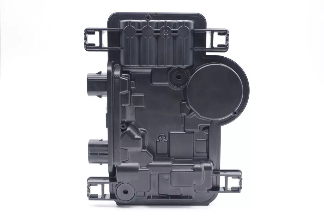
The back of the unit features irregular protrusions and recesses.
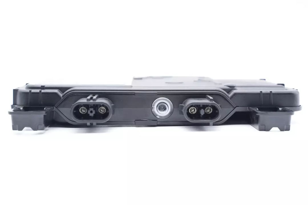
One side of the unit has two terminal connections and a status indicator.
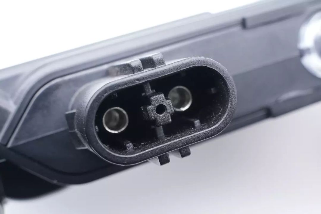
A close-up of the AC output terminals.
The left side features the AC output terminals.
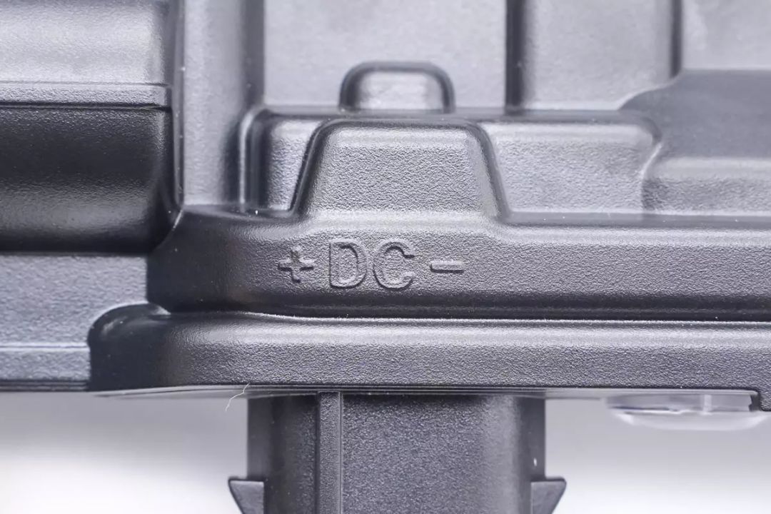
The right side has the DC input terminals.
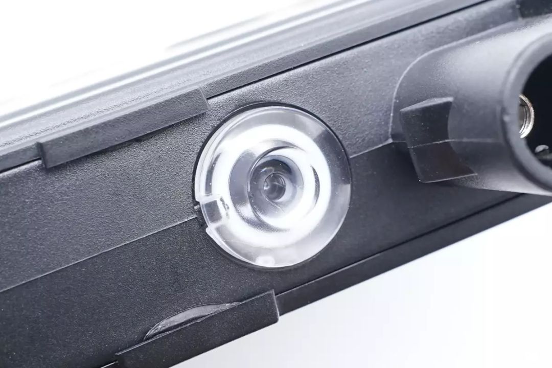
A close-up of the status indicator.
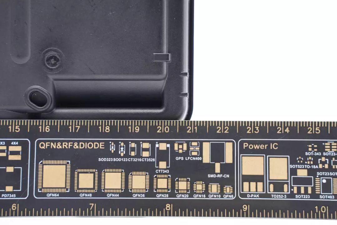
The main body of the unit measures approximately 21cm in length.

The width is approximately 12.4cm.
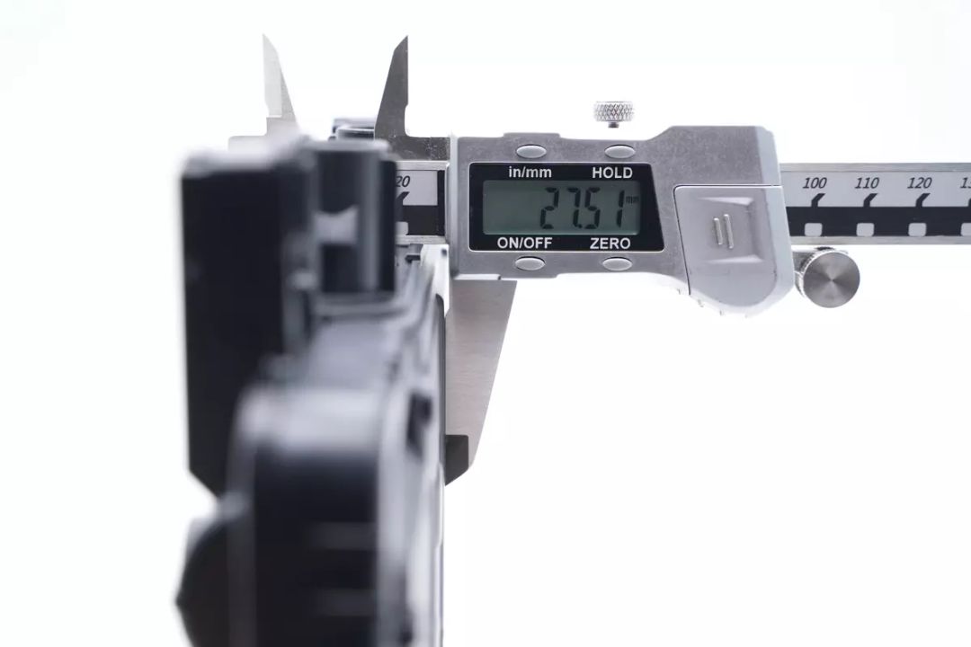
The thickness is approximately 2.8cm.
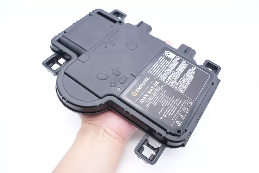
Holding the unit provides a visual sense of its size.
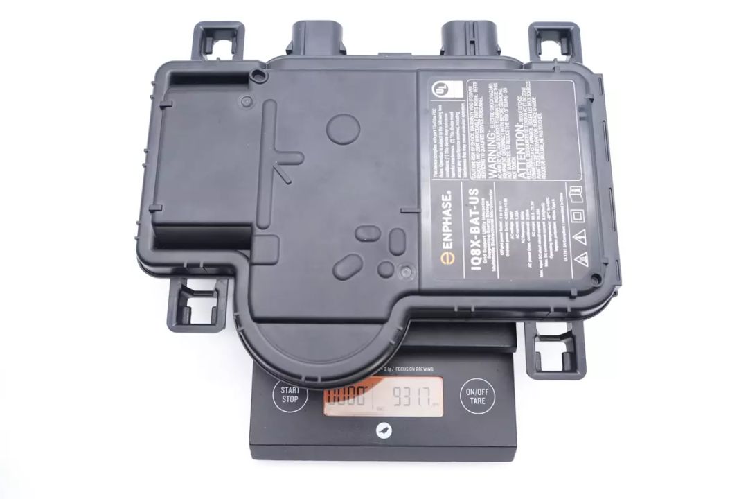
The IQ8X microinverter weighs around 932g.
ENPHASE IQ8X Micro Inverter Disassembly
After examining the exterior and interface layout, let's proceed with the disassembly to uncover the internal design and workmanship.
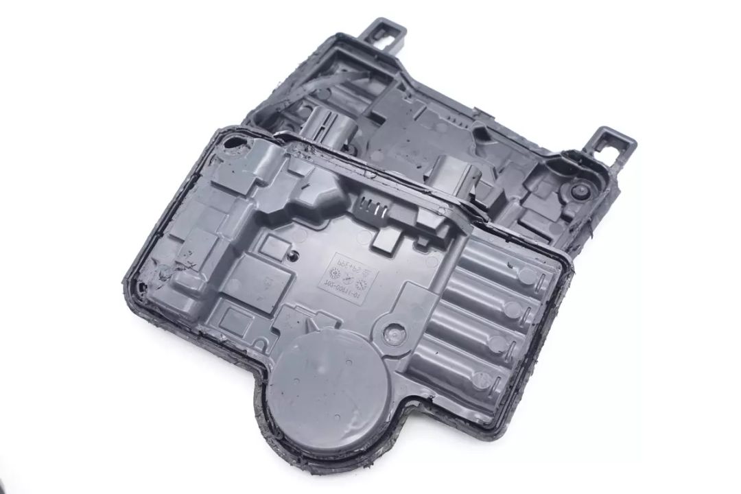
First, we use a cutting tool to open the housing, followed by the application of a heat gun to soften the adhesive and disassemble the inverter's casing.

The interior of the inverter module's housing is filled with thermal adhesive and sealed for heat dissipation.
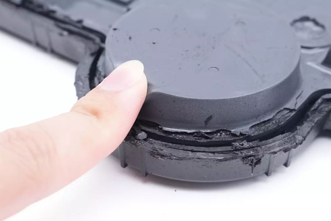
The thermal adhesive is elastic and provides excellent filling.
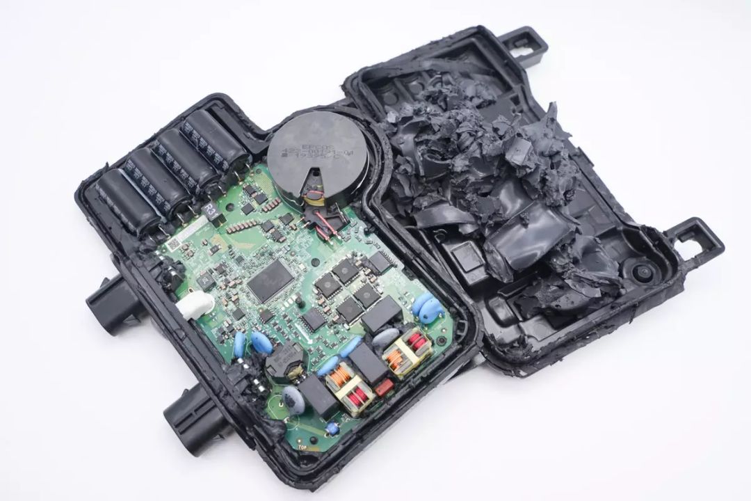
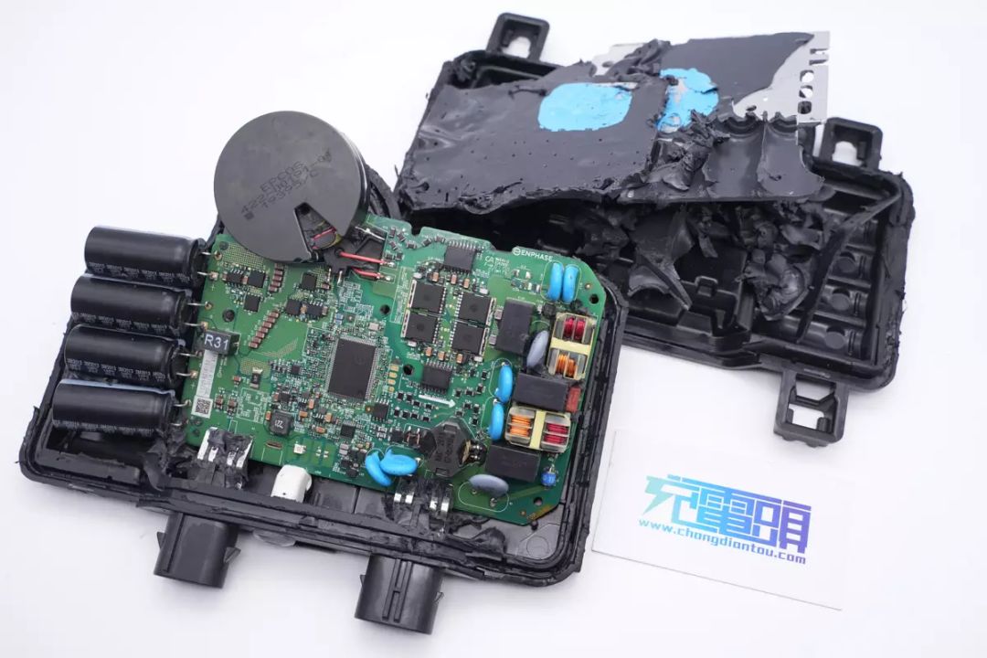
After cleaning the adhesive inside the casing, the PCBA module is exposed.
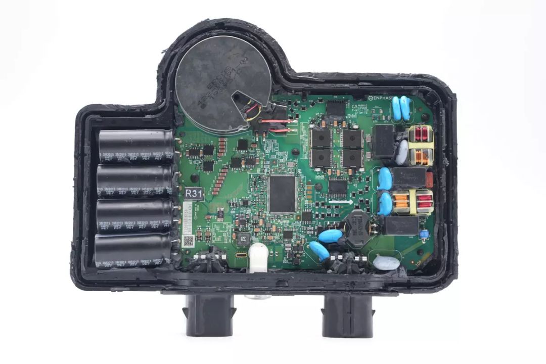
An overview of the PCBA module's interior reveals four input filter capacitors on the left side. The circular magnetic component on the upper part is the inverter transformer, while the lower part features low-voltage MOSFETs for inversion and their corresponding half-bridge drivers. In the center is the main control chip, followed by four output modulation MOSFETs, isolation drivers on the right side, and output filtering circuits and power line communication circuits on the far right.
A close-up of the DC power input terminals.
A close-up of the status indicator.

A close-up of the AC output terminals.
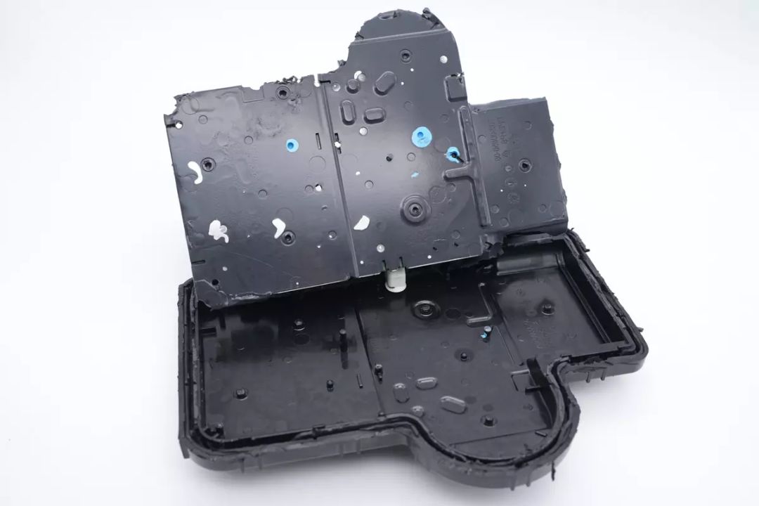
The PCBA module is removed from inside the casing, with aluminum heat sinks attached to its back.

Blue thermal compound is applied between the PCBA module and the aluminum heat sinks, with no components soldered on the back.
Two aluminum heat sinks correspond to the positions of the boost power transistors and output modulation transistors.
The DC input filter capacitors are from Rubycon, with a rating of 80V 1500μF, part of the ZLH long-life series, and are connected in parallel.
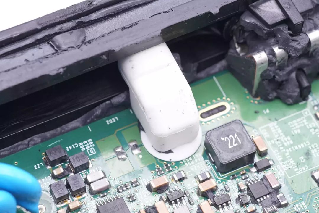
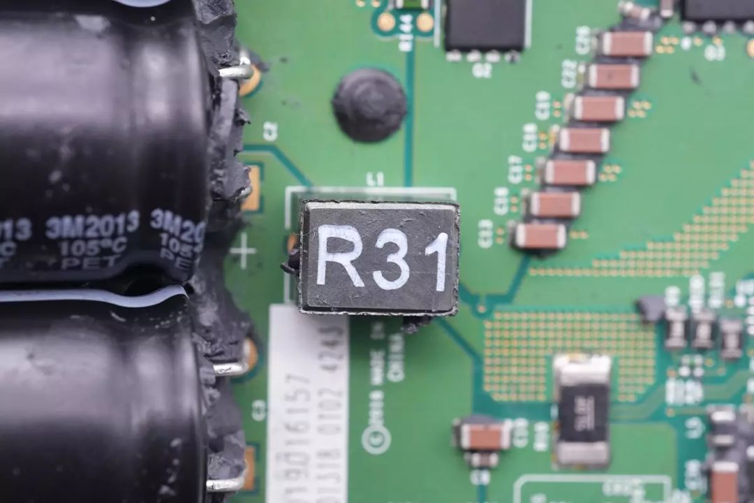
A close-up of the input filter inductor.
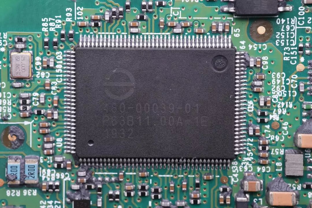
The main control chip for the inverter is from ENPHASE, with markings "480-00039-01" and "P63B11.00A-1E 1932." This chip controls the direct current boost and output modulation, with direct current boost using a half-bridge driver and AC modulation driven by isolation drivers.
A close-up of the external 25.000MHz clock crystal for the main control chip.
The external storage memory for the main control chip is from Winbond, with the model "W25Q64JVSSIQ" and a capacity of 8MB.
One buck converter chip is from Texas Instruments, with the model "LM5008," a wide input voltage range buck converter supporting 350mA output current.
Another buck converter chip of the same model.
A dual voltage comparator chip from Texas Instruments, with the model "LM2903," is used for protection and detection functions.
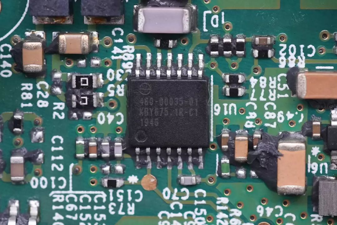
Another custom chip from ENPHASE, used for power line communication functions, with markings "480-00035-01," "KBY675.1R-C1," and "1946."
A close-up of the inductors and capacitors around the chips.
Parallel MLCC filter capacitors for direct current input.
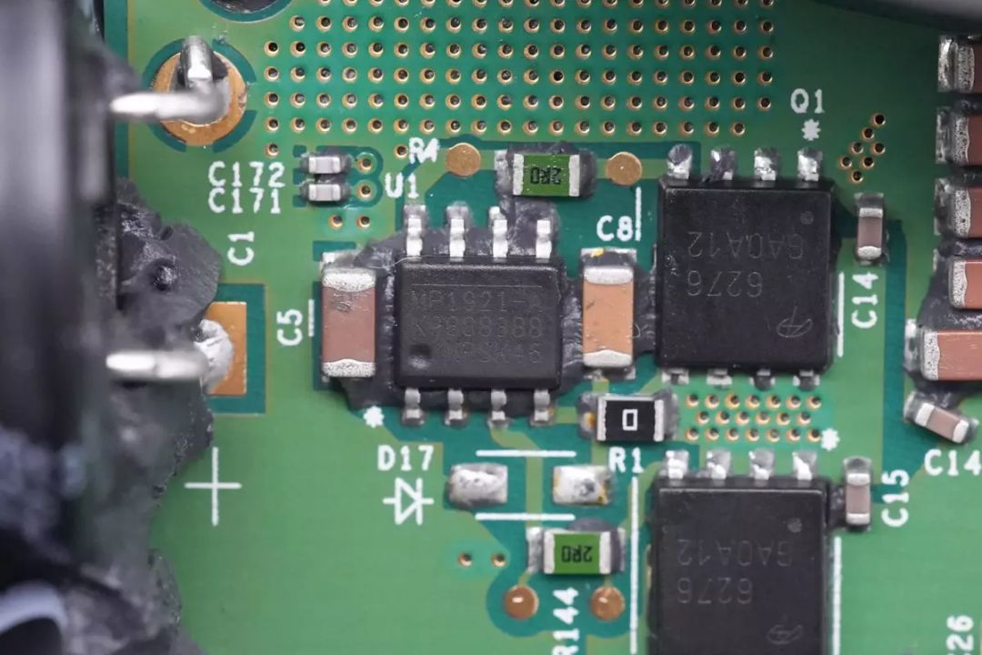
The H-bridge for the DC input uses four AOS AON6276 NMOS transistors, with an 80V rating and 2.2mΩ on-resistance, in a DFN5*6 package.
A close-up of the AON6276 transistors.
The drivers for low-voltage MOSFETs are from MPS, with the model "MP1921A," a 100V half-bridge driver with an integrated bootstrap diode. It allows independent control of the upper and lower transistors.
Another close-up of the driver.
The inverter transformer is from EPCOS, featuring a circular magnetic core and integrated output current sensor.
The output insulation wire passes through the current sensor.
The four output modulation MOSFETs are from Infineon, marked as 60R102G7, with the actual model being IPT60R102G7. They have a voltage tolerance of 650V and a resistance of 102mΩ, packaged in TOLL format.
Two isolation drivers come from Texas Instruments, with the model UCC21520A. They are dual-channel isolation drivers used for driving the output modulation MOSFETs.
Another driver shares the same model.
The X2 safety capacitors, with a capacitance of 0.33μF, are highlighted.
One output-side varistor comes from EPCOS and belongs to the SNF14 series, used for overvoltage protection.
A TVS diode is connected in series with the varistor for overvoltage protection.
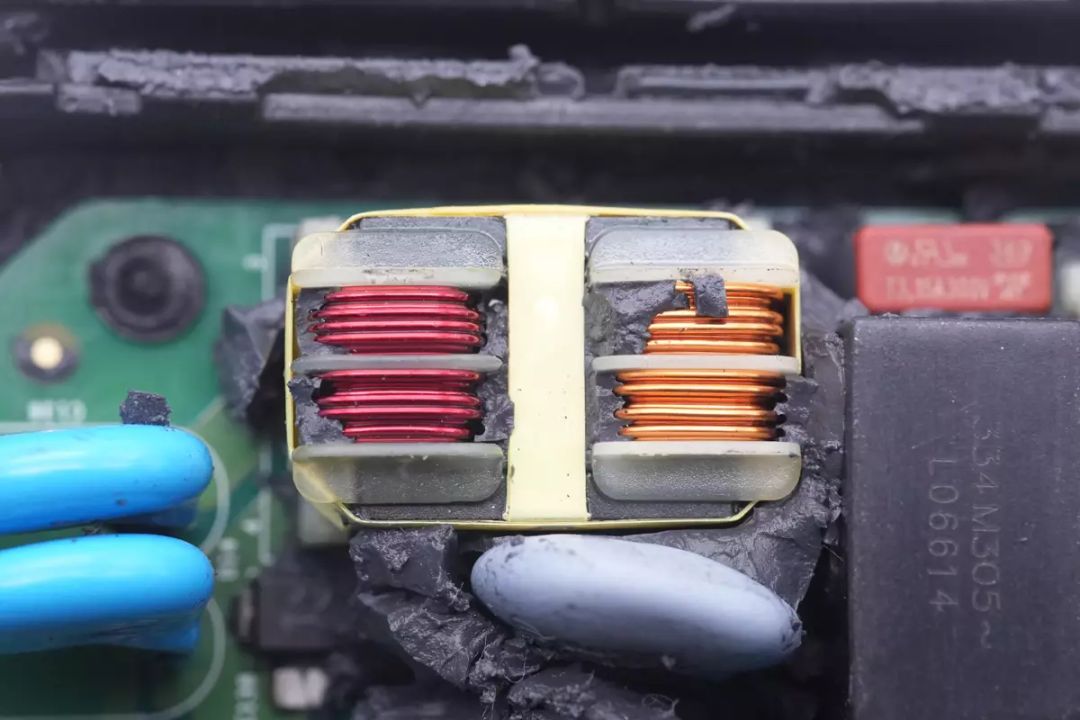
The common-mode inductors are wound with red and copper enameled wire, with the core wrapped in insulating tape.
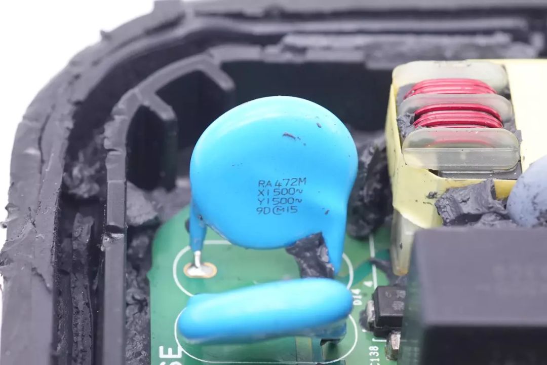
Two blue Y capacitors are shown.
The X2 safety capacitors, with a capacitance of 0.33μF, are emphasized.
The output fuse is from Littelfuse, with a rating of 3.15A 300V.
Another common-mode inductor is highlighted.
The X2 safety capacitors, with a capacitance of 0.33μF, are again featured.
A gas discharge tube and varistor are connected in series for overvoltage protection.
The output-side varistor, from EPCOS, belongs to the SNF14 series.
Two Y capacitors on the output side are displayed.
A transformer for power line communication modulation is visible.
Two more blue Y capacitors are depicted.
With everything disassembled, here's a family portrait.
Charging Head Network's disassembly conclusion
ENPHASE's microinverter product line is extensive. It includes the IQ7 series for grid-connected power generation and the IQ8 microinverter designed for battery energy storage applications. These microinverters are configurable through power line communication, allowing for adjustments to output voltage and other parameters. The IQ8 model can provide power even during outages, meeting the demand for energy storage supply.
Through the disassembly, Charging Head Network discovered that this microinverter by ENPHASE is modular in design and features a robust plastic casing. The internal components are sealed with adhesive, offering excellent weather resistance. The PCB inside is equipped with thermal compound and heat sinks for efficient heat dissipation. The microinverter utilizes a custom-made main control chip, MPS drivers in the boost stage in combination with AOS switching transistors, and Infineon modulation drivers with their corresponding switching transistors. All the components used are from top-tier brands, and when combined with the sealing process, they enhance heat dissipation capabilities, making the microinverter suitable for demanding outdoor environments.
recommend

Jan 15, 2024
The Q3 2023 global best-selling smart door locks market analysis by Chaodian Intelligence is based on the sales data of ...
Hot