Hoymiles is a Chinese high-tech enterprise specializing in the research, development, manufacturing, and sales of power conversion equipment, electrical complete sets of equipment, and related products such as photovoltaic inverters. Their product range includes microinverters for solar energy, energy storage inverters, and energy monitoring and data acquisition devices. Charging Head Network acquired one of Hoymiles' solar microinverters, the MI-700, with a 700W output power capacity, featuring two sets of direct current (DC) inputs from solar panels and one alternating current (AC) output.
This solar microinverter is designed for waterproofing, featuring an all-aluminum enclosure, and reinforced with an aluminum alloy backplate for heat dissipation. The screw fasteners make disassembly easier. Let's dive into the disassembly of this Hoymiles solar microinverter and explore its internal design and components.
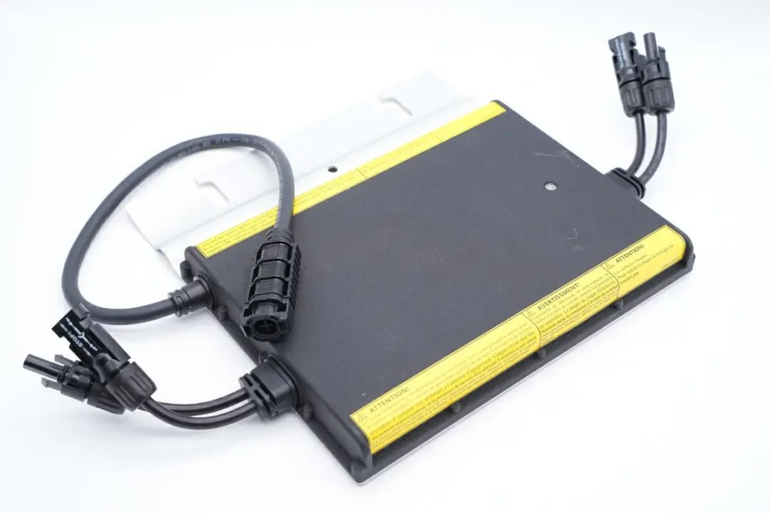
The Hoymiles MI-700 microinverter has an all-aluminum casing with aluminum alloy cover plates, including three sets of connection wires on both sides.
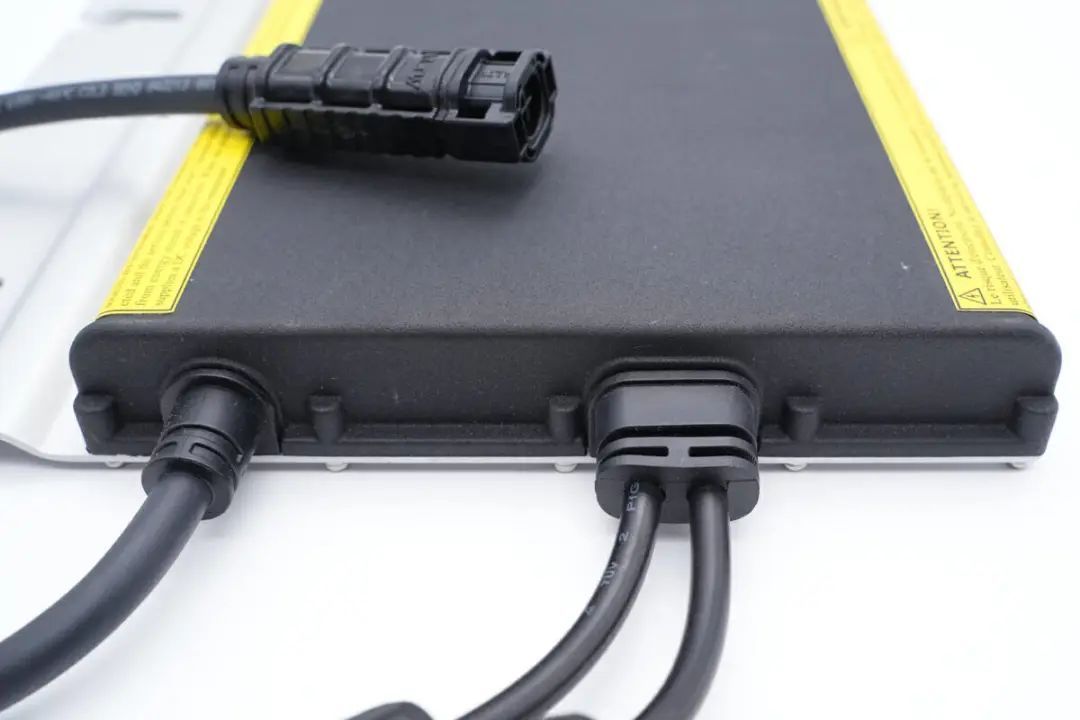
The connection wires on both sides are designed with bend-resistant protection,
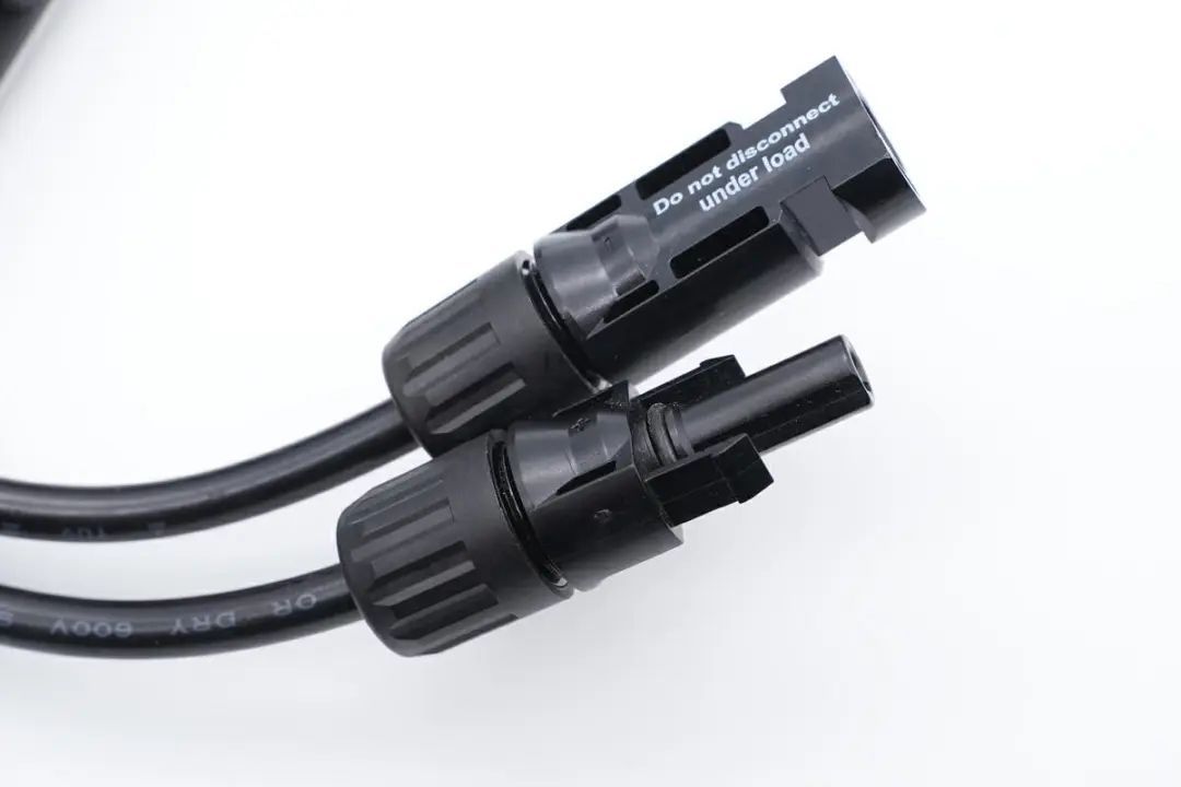
and the connector ends have latching mechanisms and grooves for secure connections.
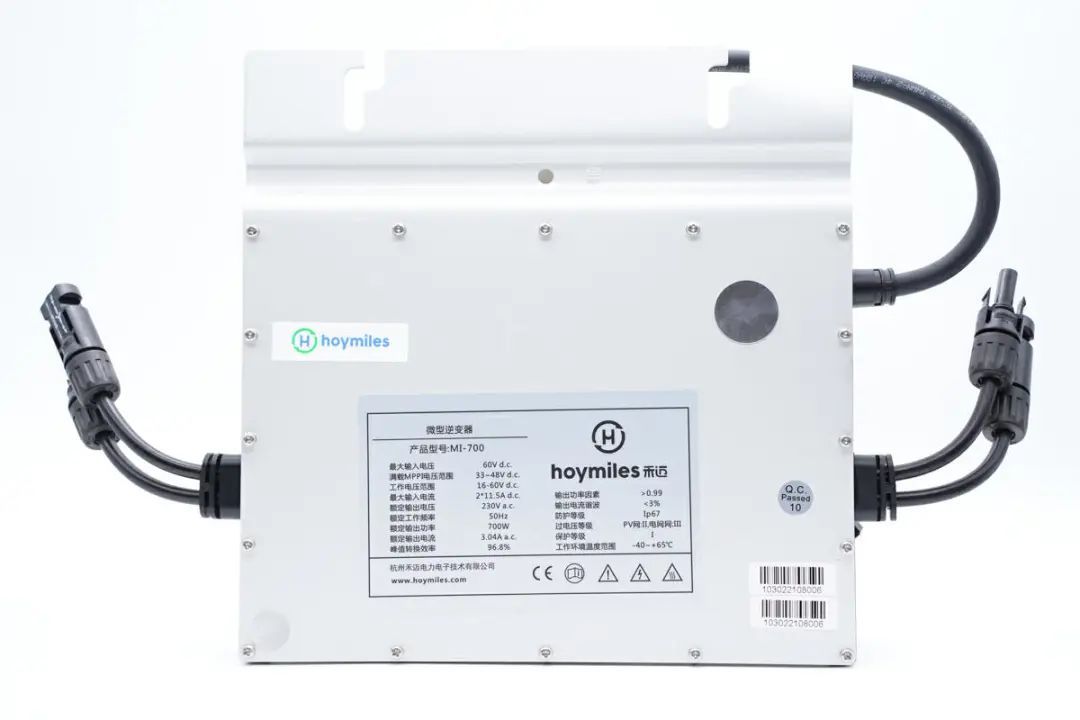
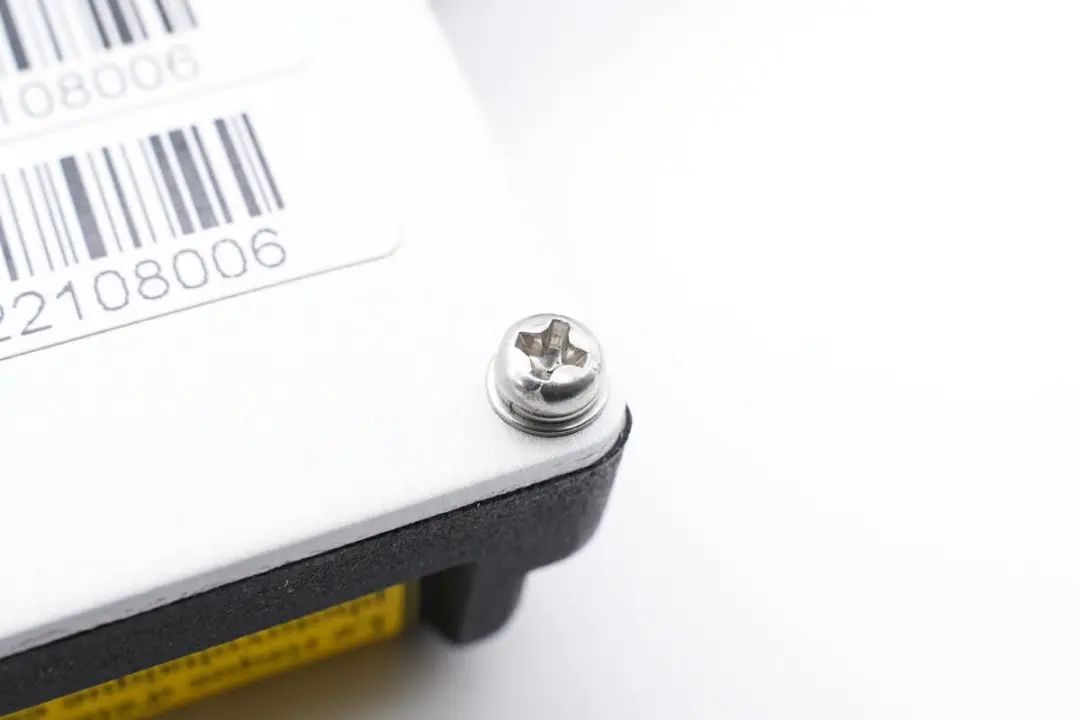
The back of the device has a total of 16 screws along the edges.
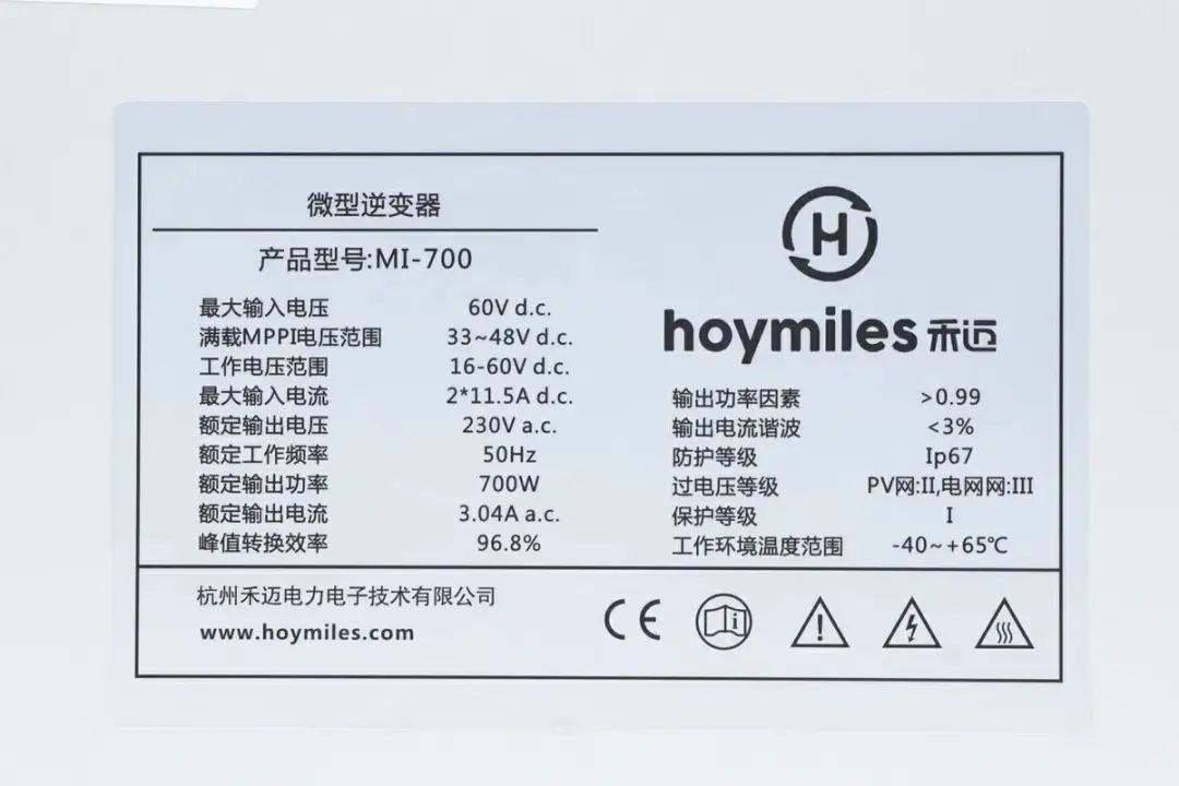
The product label provides the following details:
Product Model: MI-700
Maximum Input Voltage: 60V DC
Full Load Maximum Power Point Input Voltage Range: 33-48V DC
Operating Voltage Range: 16-60V DC
Maximum Input Current: 2*11.5A DC
Rated Output Voltage: 230V AC
Rated Frequency: 50Hz
Rated Output Power: 700W
Rated Output Current: 3.04A AC
Peak Conversion Efficiency: 96.8%
Output Power Factor: >0.99
Output Current Harmonics: <3%
Protection Level: IP67
Operating Temperature Range: -44 to +65°C
Manufactured by Hangzhou Hoymiles Power Electronics Co., Ltd.
Product certified with CE.
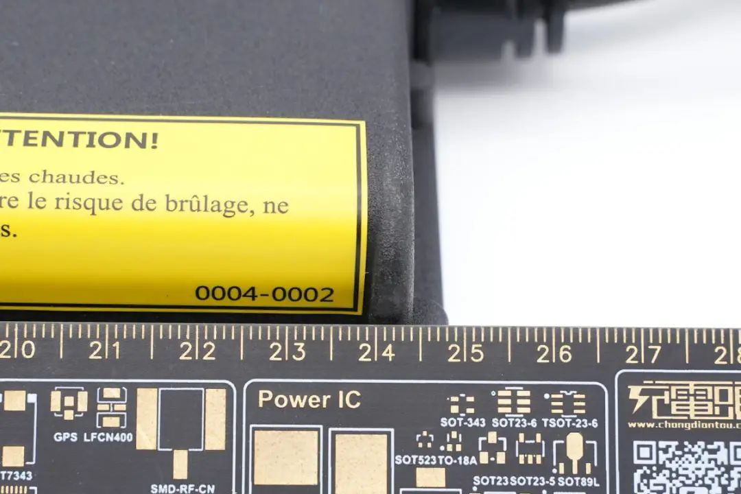
The length of the inverter unit measures approximately 24.5 cm,
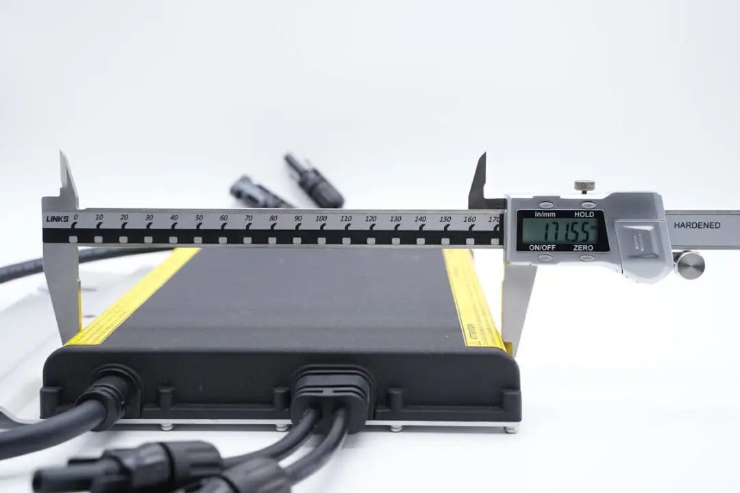
the width is 171.55 mm,

and the thickness is 27.9 mm.

A comparison with an adult's palm provides a visual understanding of the size.
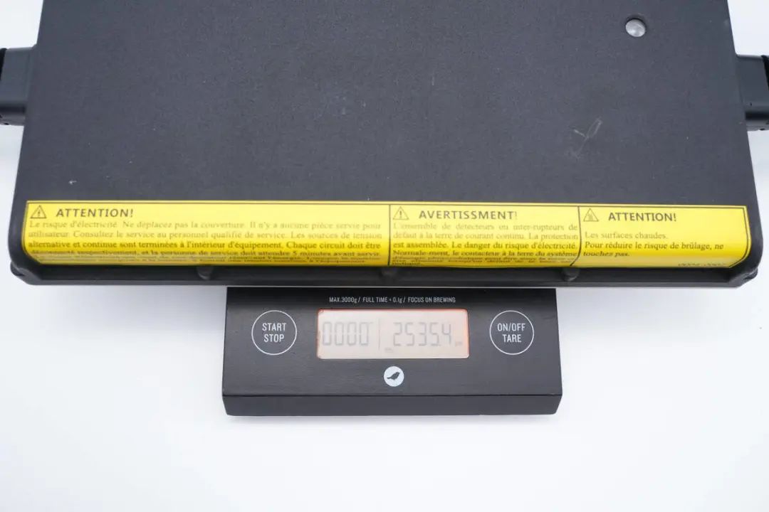
The net weight of the microinverter is approximately 2535g.
Disassembly of the Hoymiles Microinverter
After examining the exterior of the microinverter, let's proceed with the disassembly to explore its internal design and components.
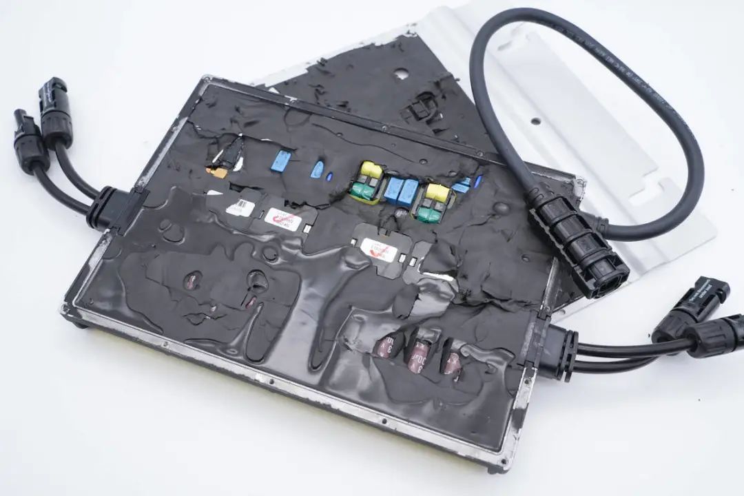
The microinverter features an aluminum alloy cover plate fixed by screws, making disassembly relatively straightforward. By removing the edge screws, the aluminum alloy outer casing can be separated.
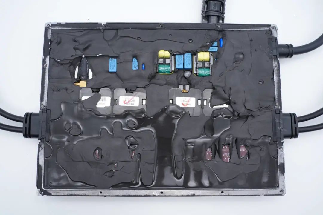
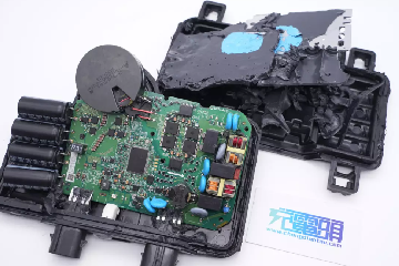
Inside the plastic housing, black thermal conductive adhesive is used to dissipate heat from the heat-producing components and provides cushioning.
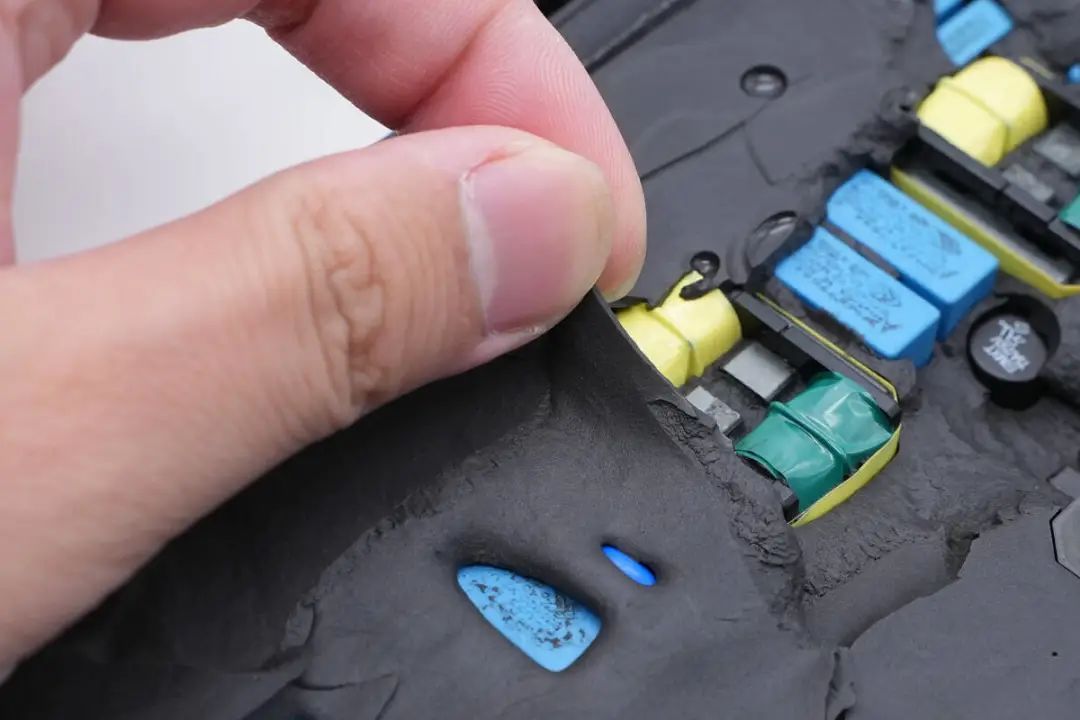
The thermal adhesive has a degree of flexibility, effectively filling gaps between components.
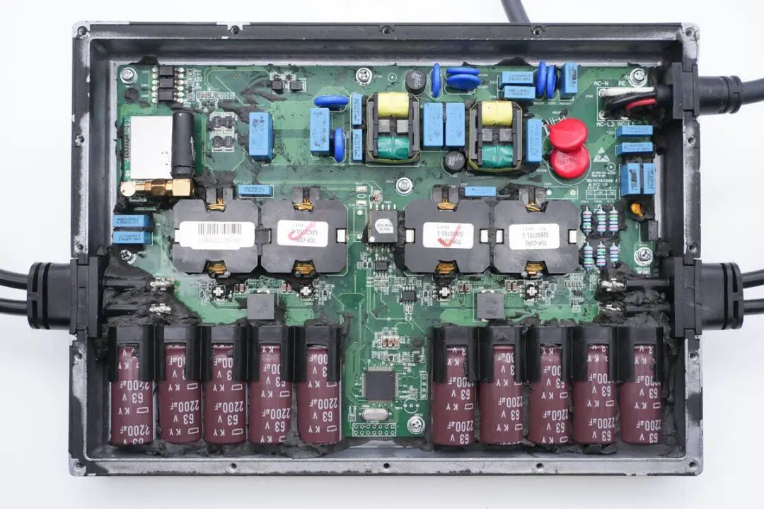
With the thermal adhesive removed, the inspection of component information on the PCB module inside the inverter begins.
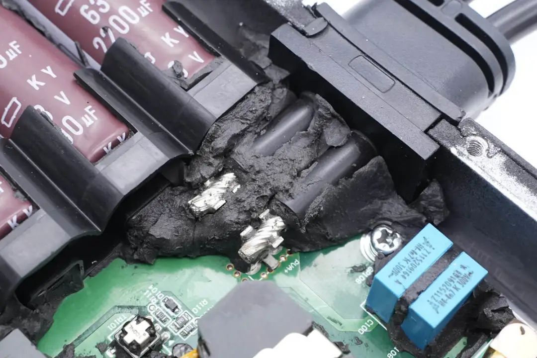
The PCB module is secured inside the housing with screws.
The DC input wires on the left side are soldered to wire terminals on the PCB.
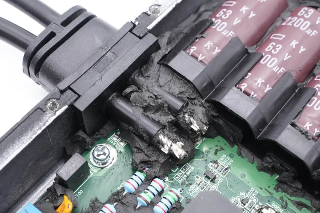
The DC input wires on the right side are also soldered in a similar fashion.
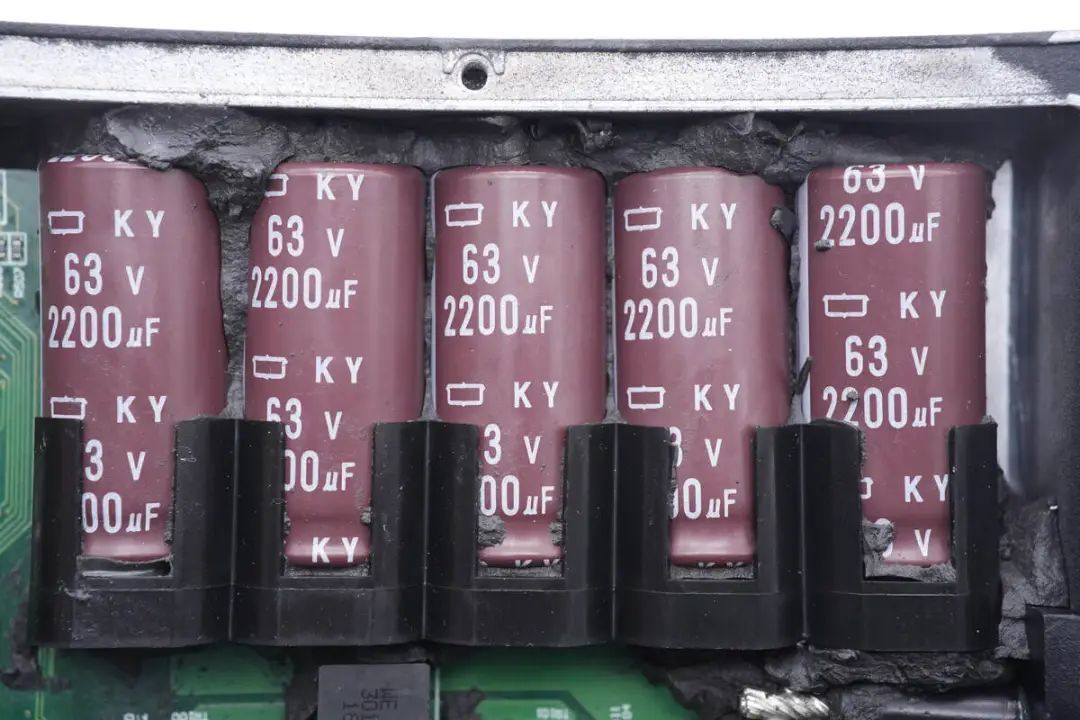
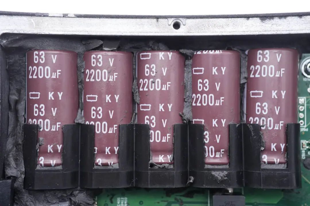
Five filter electrolytic capacitors, from Guimigong's KY series with a specification of 63V 2200μF, are secured with plastic brackets.
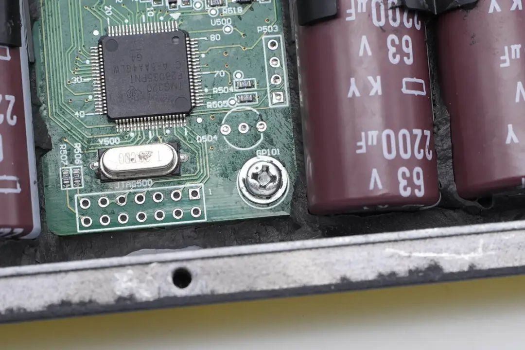
Another set of five capacitors corresponds to the other side's DC input. The PCB module is fixed inside the casing with screws.
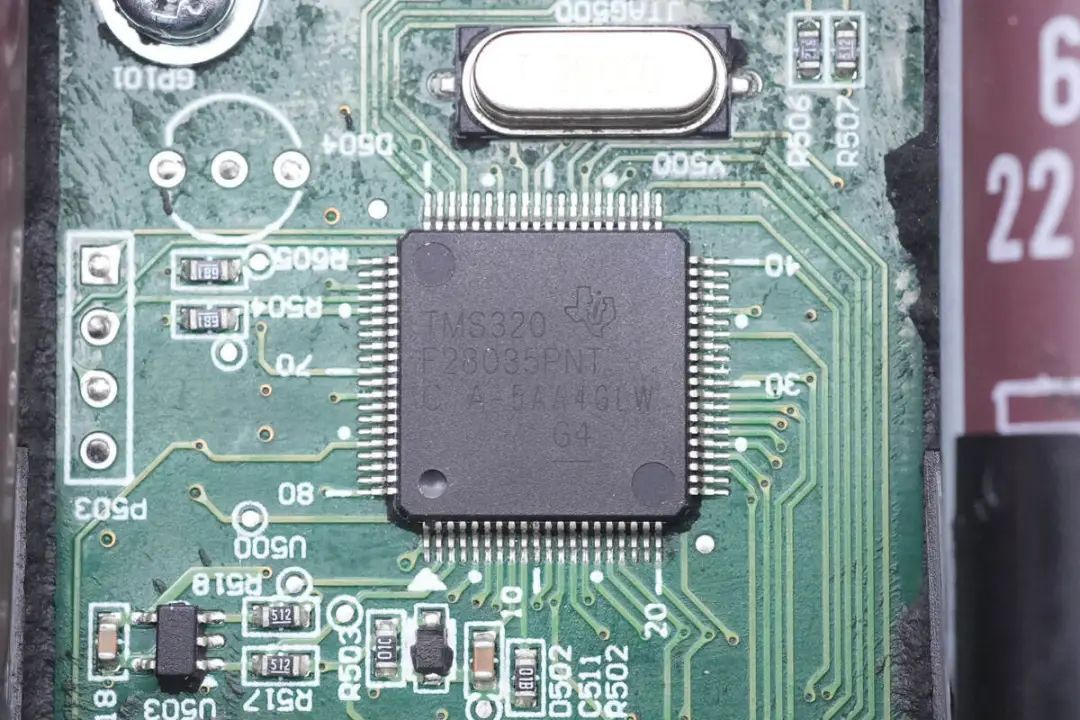
The inverter's main controller is from Texas Instruments (TI) and is labeled TMS320F28035. This is a 60MHz microcontroller unit (MCU) with 128KB of Flash memory, belonging to the C2000 series. The chip includes a 12-bit analog-to-digital converter (ADC), supports various serial interfaces such as UART, SPI, I2C, and provides PWM signal outputs and various peripherals.
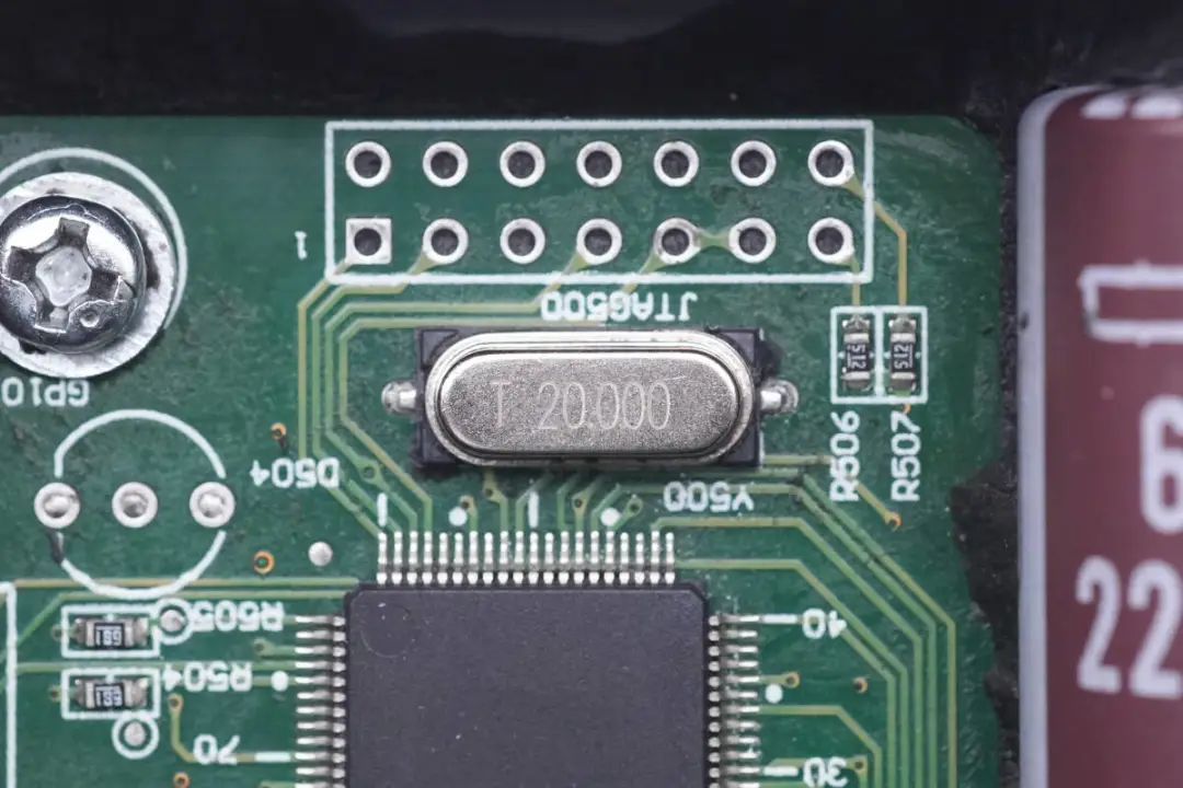
A surface-mount 20MHz crystal oscillator is featured externally.

Input side filter inductors come from Wurth.
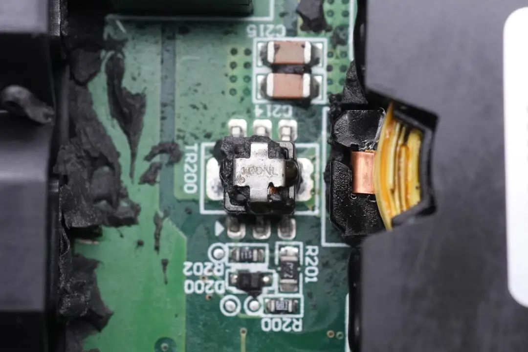
Surface-mount current transformers are used for primary current detection.

Another set of current transformers is examined.
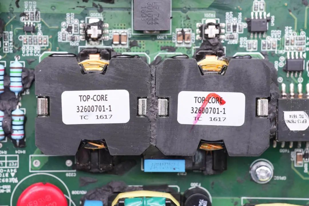
Boost transformers are also featured, with a label on the top and metal spring clips on the sides for securing.
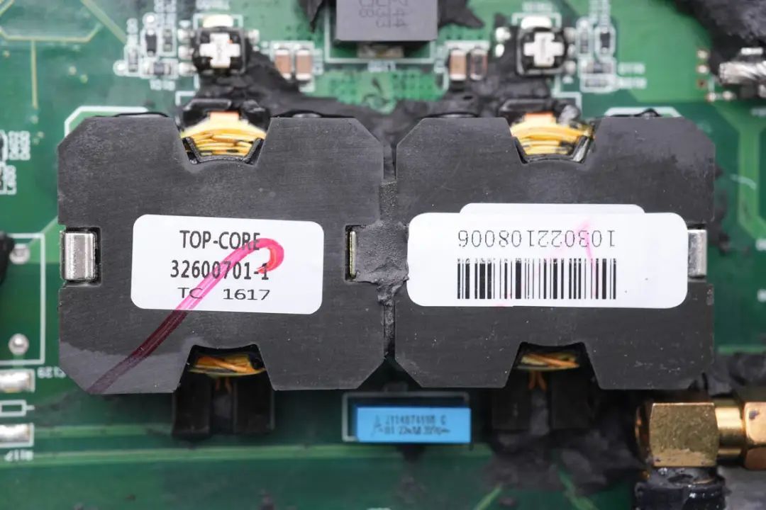
Another pair of transformers corresponds to the second boost circuit.
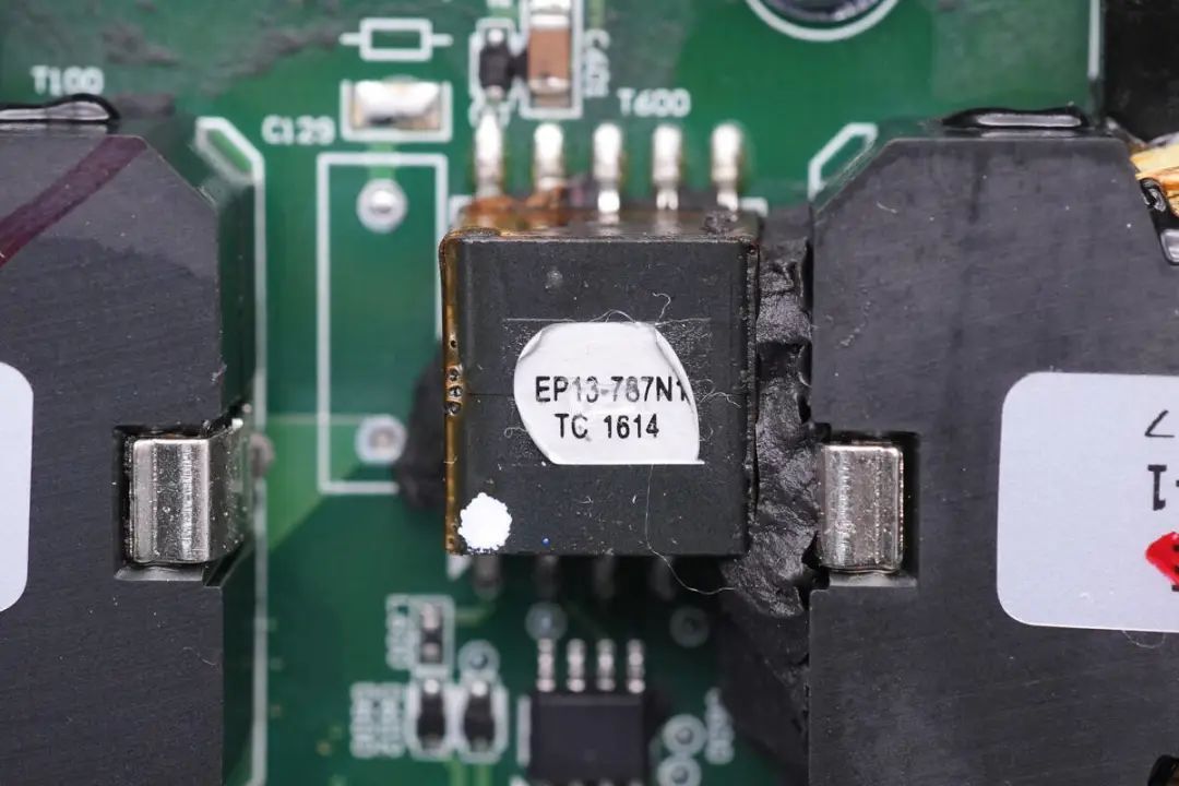
Between the two groups of transformers, there is an isolation transformer for power supply separation.
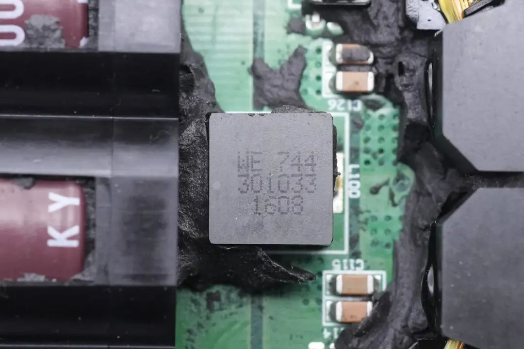
The other boost circuit's filter inductor is also visible,

along with the corresponding current transformer.
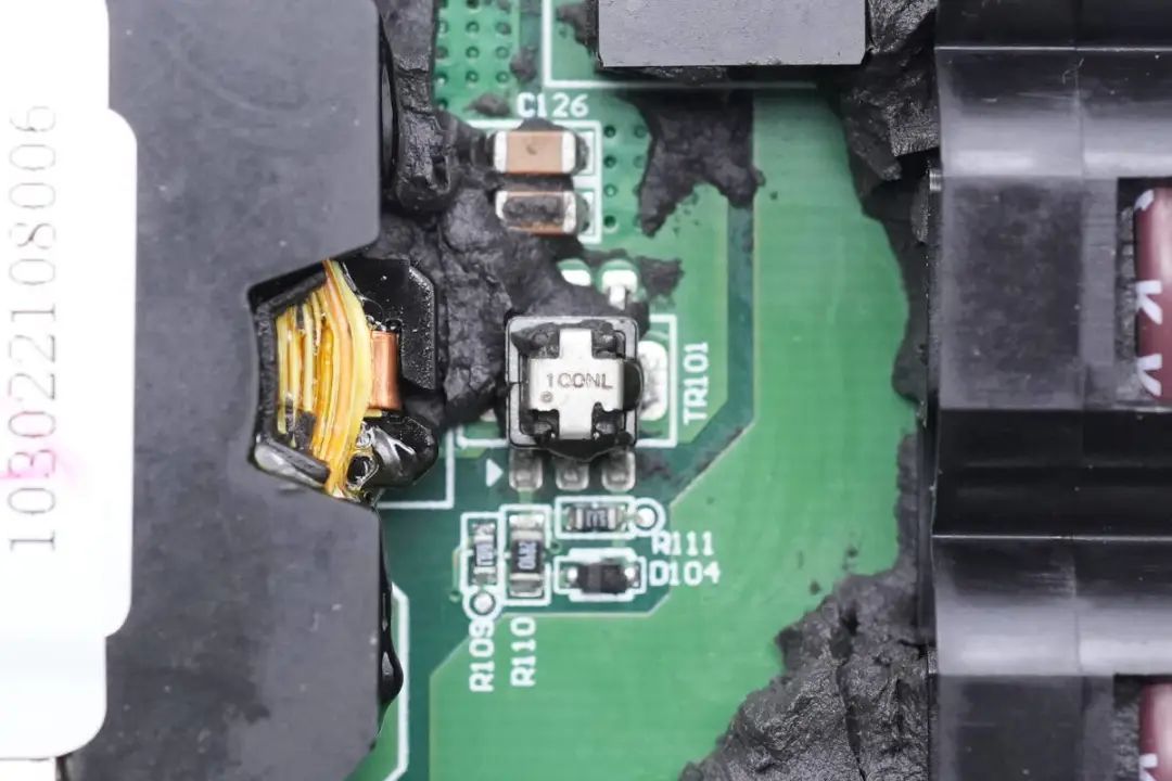
Another current transformer is highlighted.
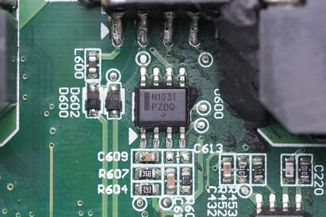
The ON Semiconductor NCP1031 DC-DC converter is used for power supply isolation.
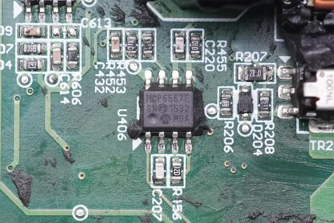
The MCP6567, a dual voltage comparator from Microchip, is used for protective monitoring.

Voltage divider resistors are used for input voltage detection.
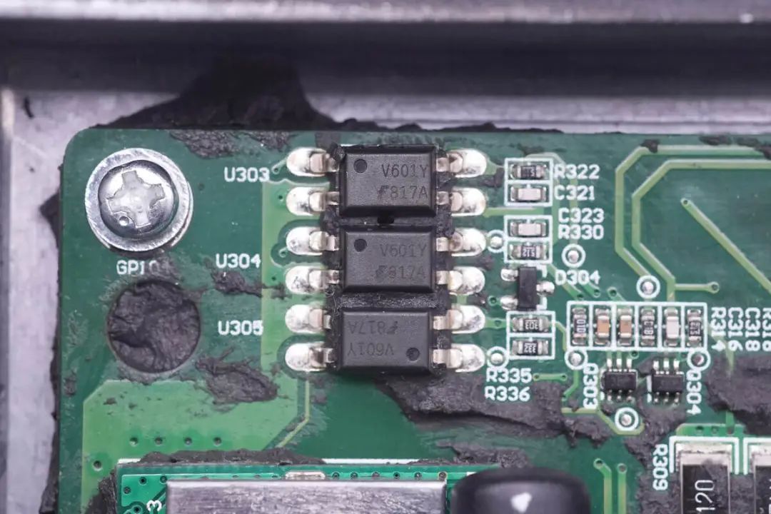
An 817A optocoupler is soldered on the top left corner of the PCB for isolation drive.
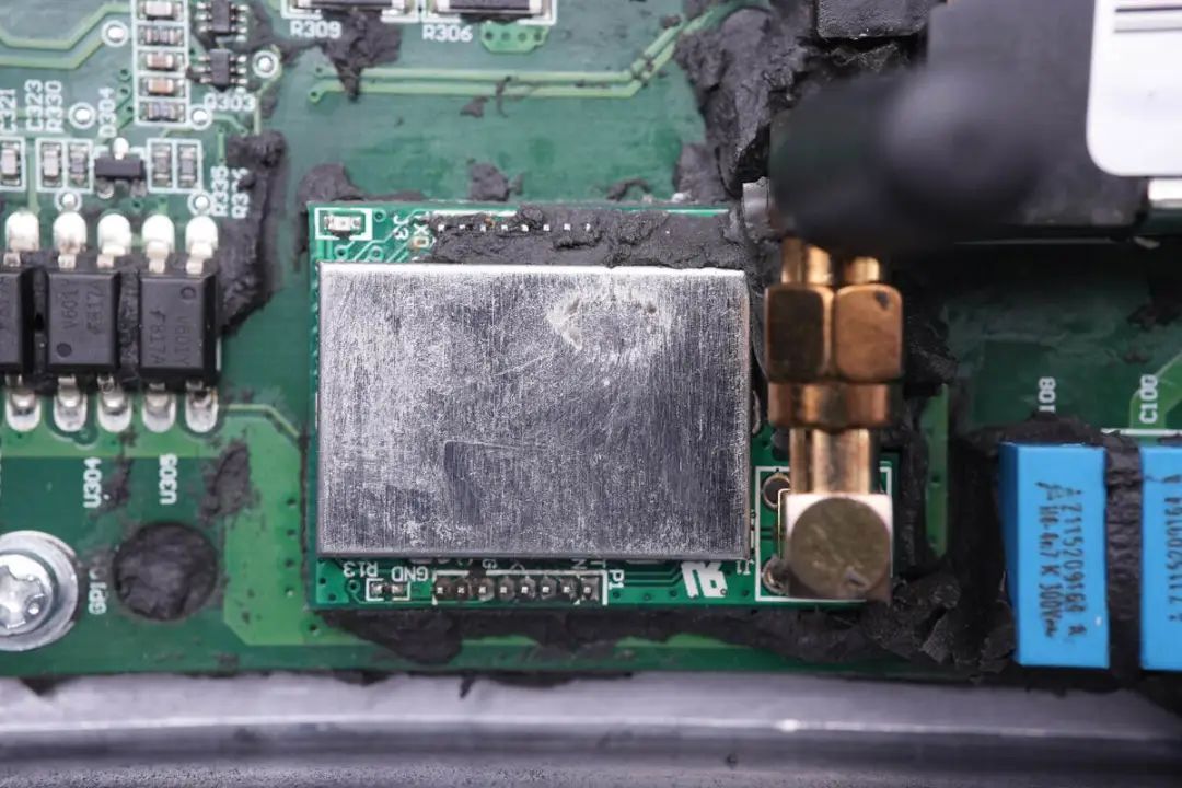
On the PCBA module, a wireless communication module is soldered for communication between the inverter and a controller,
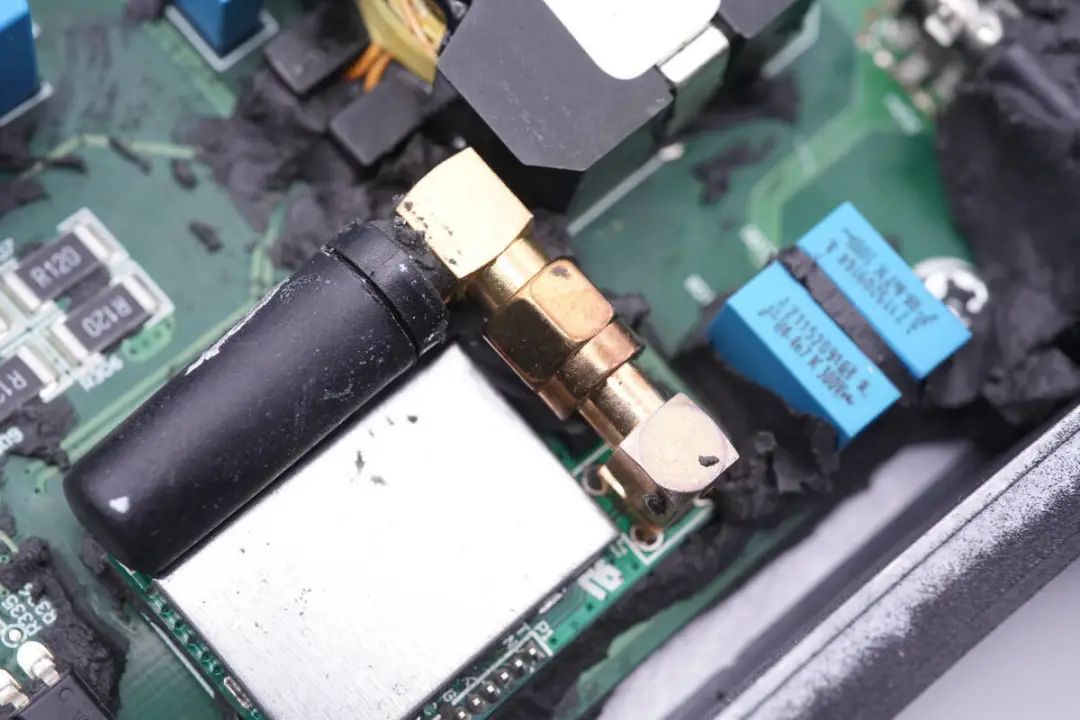
with an antenna connector highlighted.
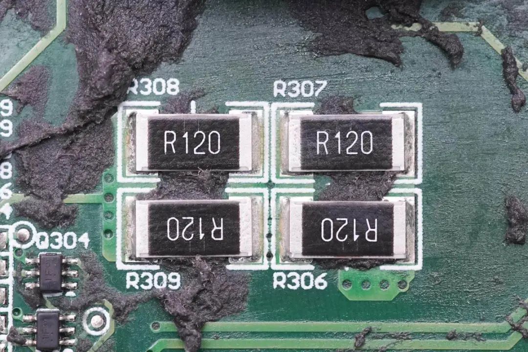
Four 120mΩ resistors are connected in parallel to increase power.
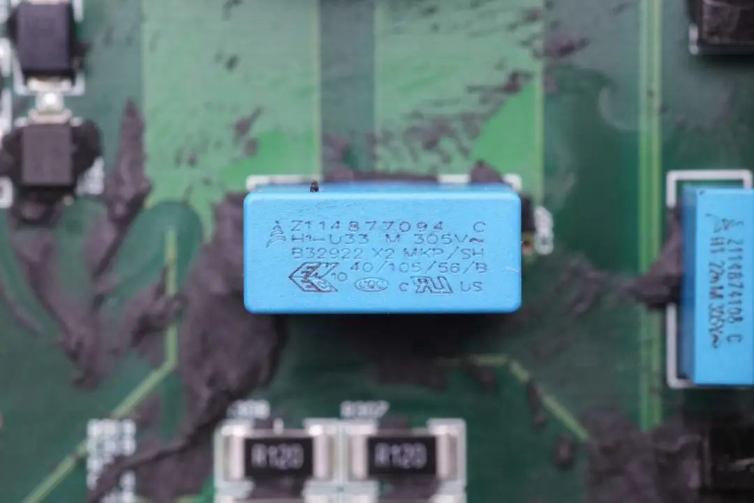
X2 safety capacitors from EPCOS, with a capacitance of 0.33μF, are shown.
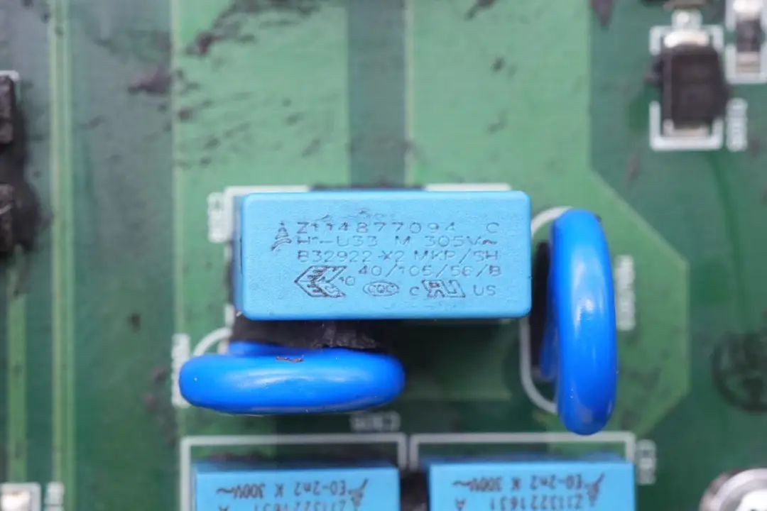
Another X2 safety capacitor with the same specifications is featured.

Varistors from TDK's S14 series are used for overvoltage protection,
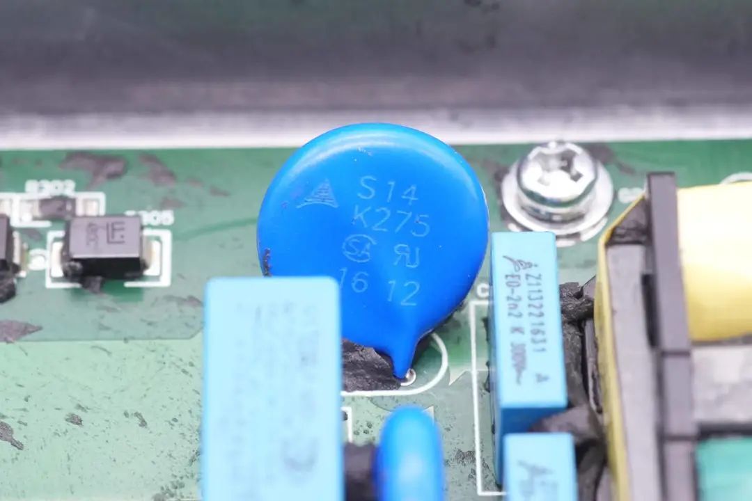
with another pair of varistors of the same series.
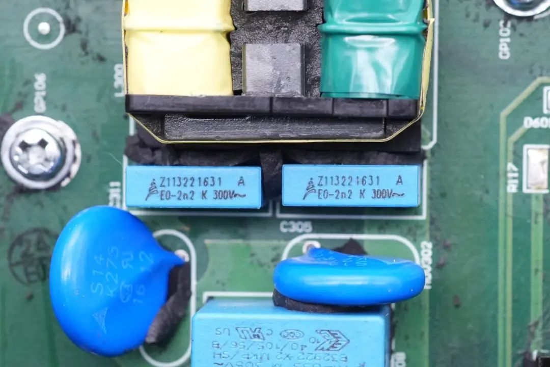
Two 2.2nF 300V film capacitors are visible,
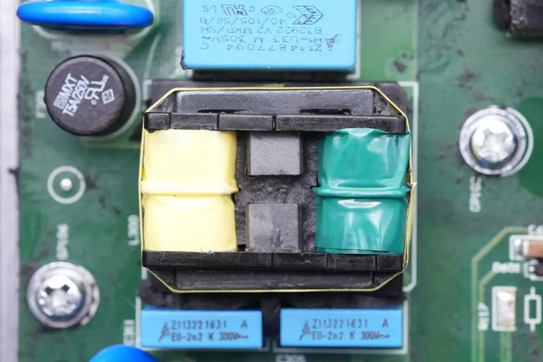
and a close-up of a filter inductor is provided.
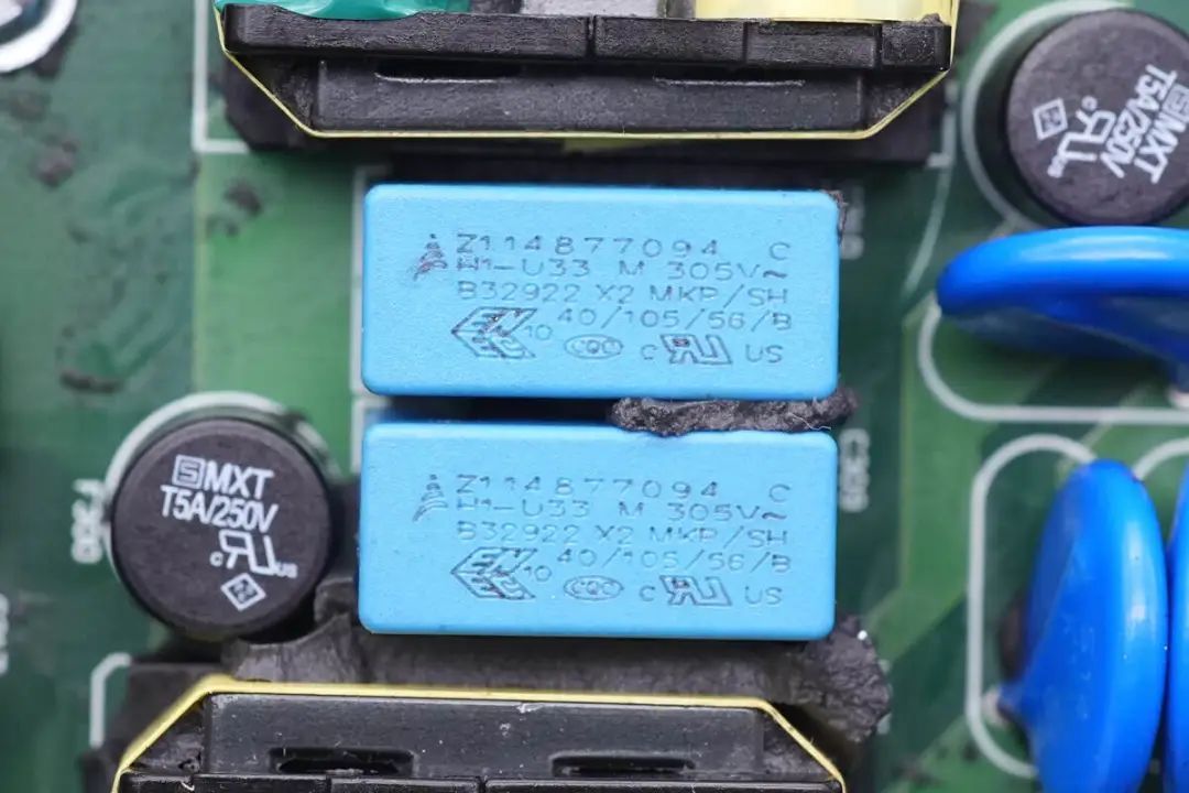
In between the two filter inductors, there are two 0.33μF X2 safety capacitors.
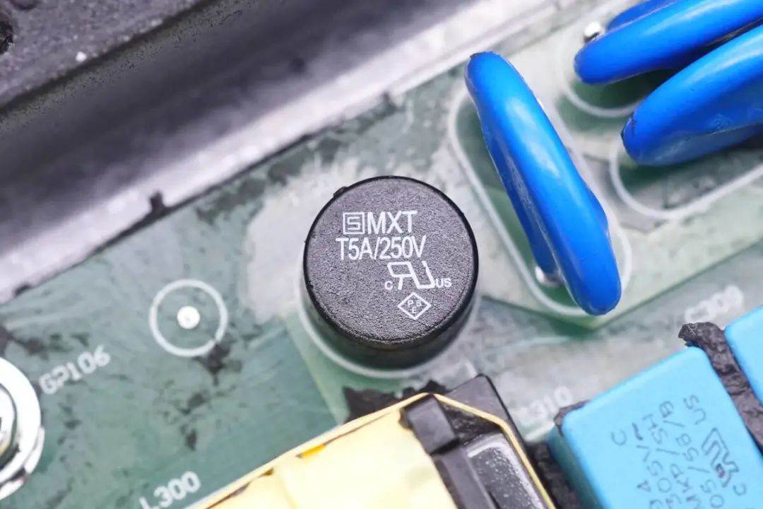
A pair of AC circuit fuses, rated at 5A 250V, are highlighted,

along with another set of fuses with the same rating.
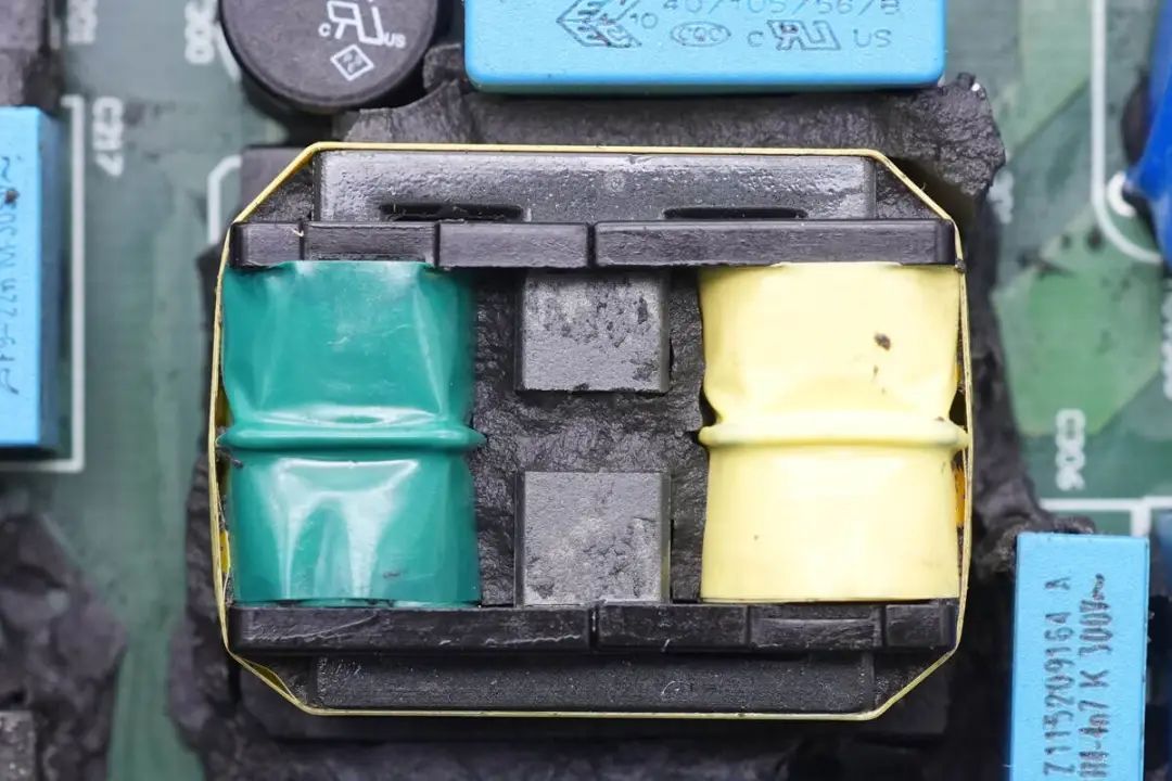
Another view of the filter inductor is provided.
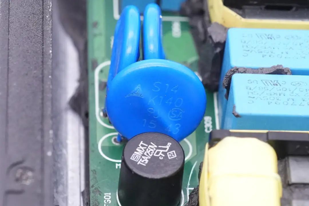
For overvoltage protection,varistors from TDK's S14 series are highlighted.
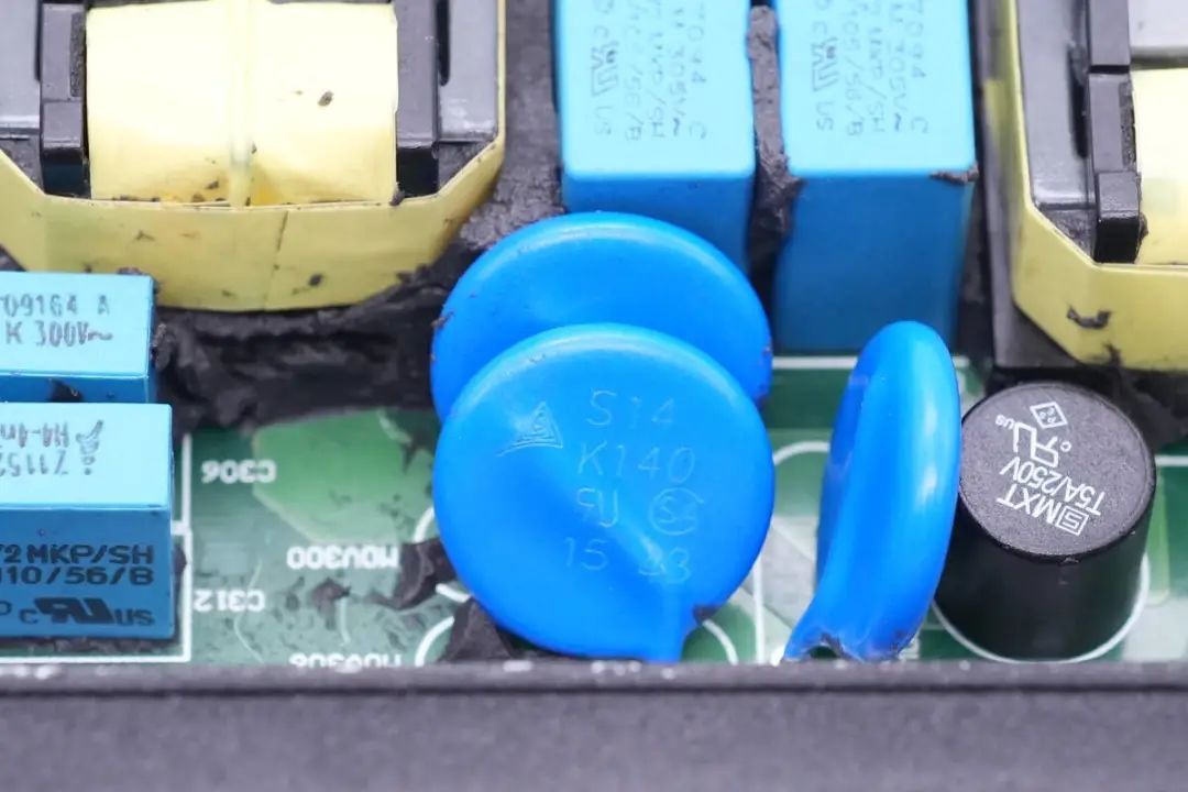
Two additional varistors from the same series are also featured.

Two 4.7nF film capacitors are shown.
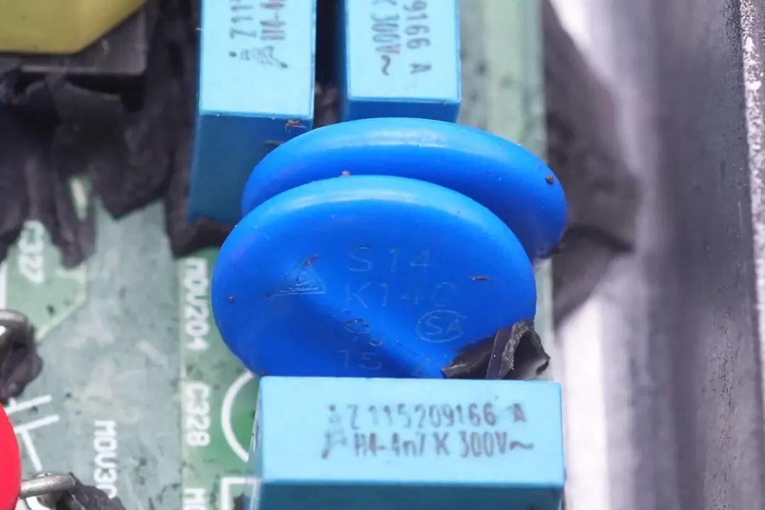
The pair of varistors is also from TDK's S14 series.
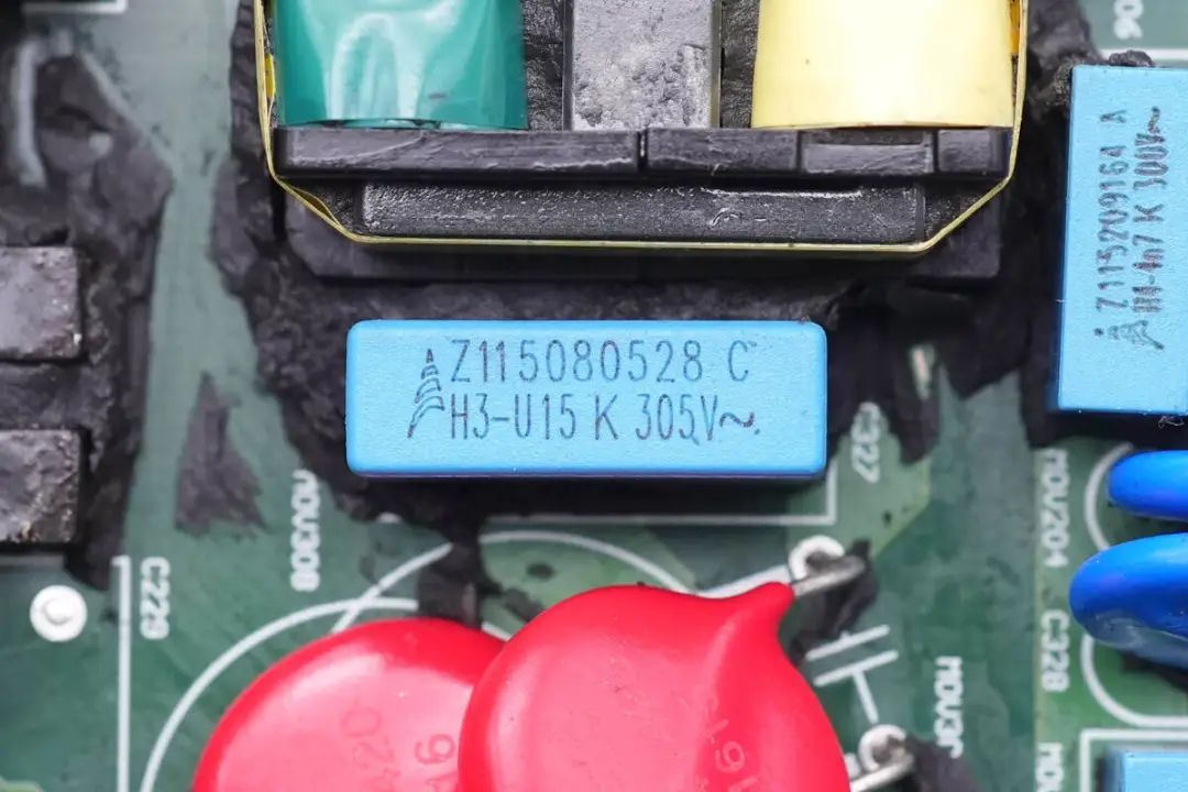
The X2 safety capacitors have a capacitance of 0.15μF.
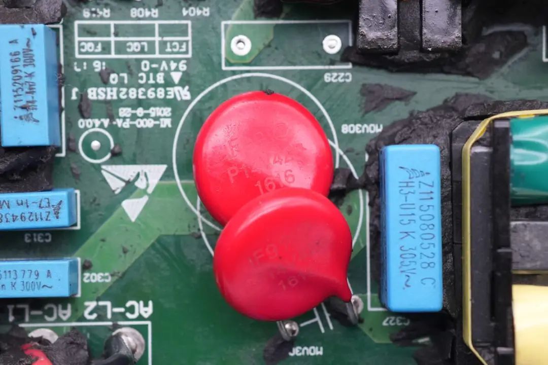
Two red varistors are used for output overvoltage and surge protection.
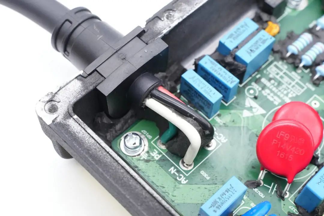
The AC output terminals use direct wire soldering.
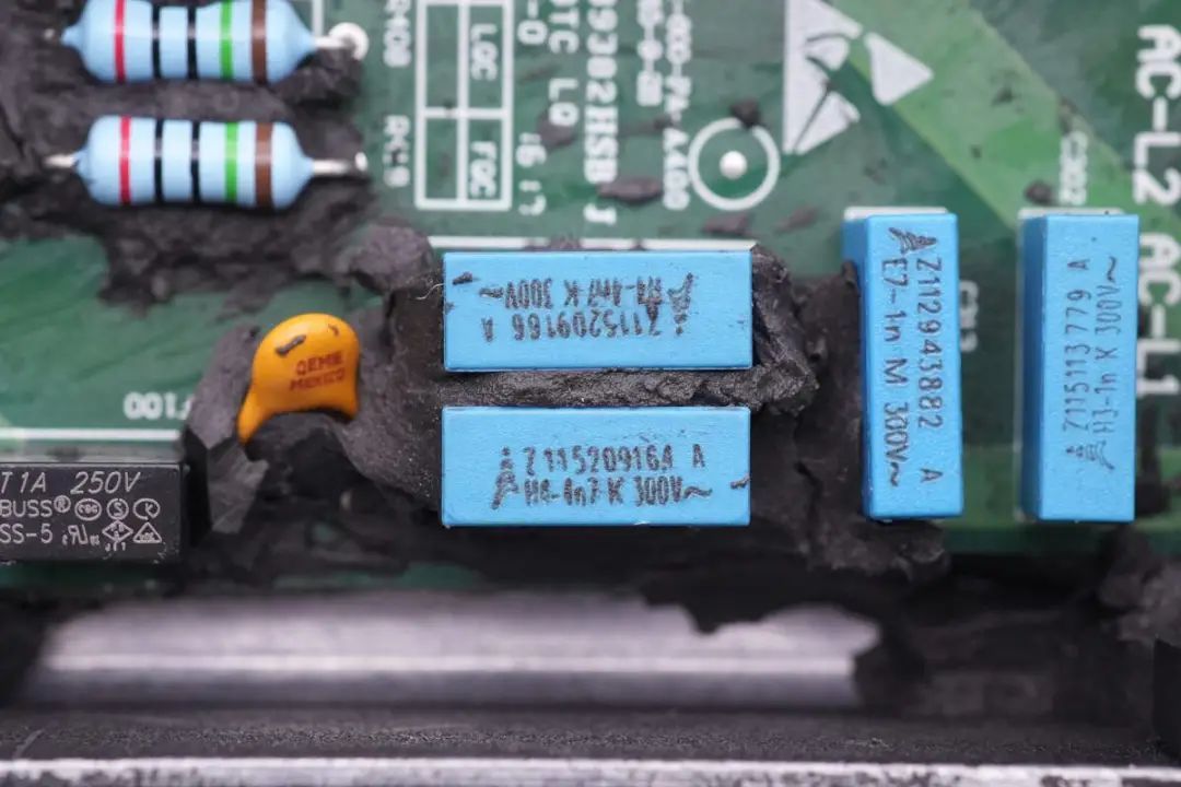
Two 4.7nF 300V film capacitors come from EPCOS.
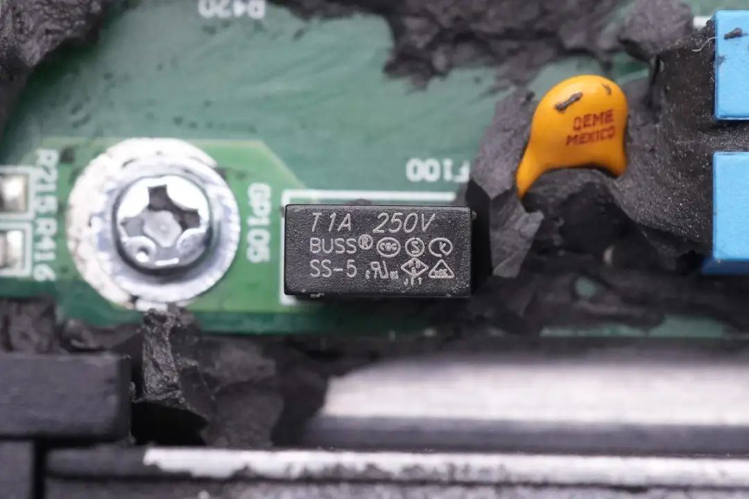
The fuse specifications are 1A 250V.
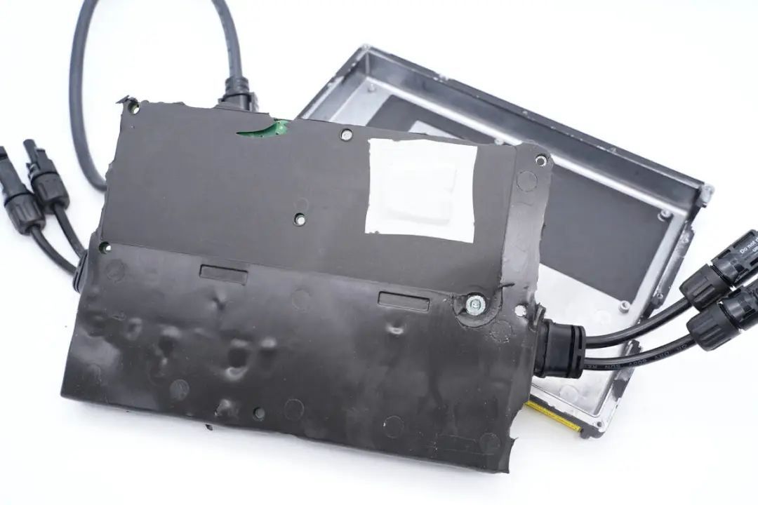
Turning to the back of the PCBA module of the inverter, thermal pads are attached to the positions corresponding to power devices on the mainboard to aid in heat dissipation.

Inside the housing, insulating mylar sheets are adhered.
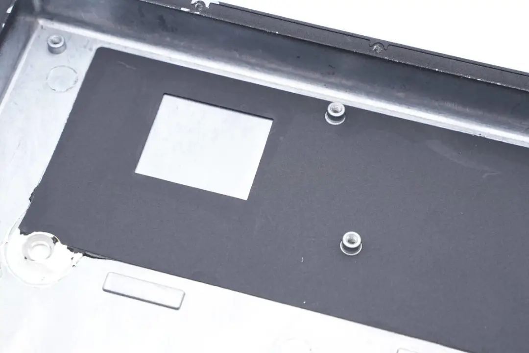
The holes in the mylar sheets align with the power device positions on the mainboard.
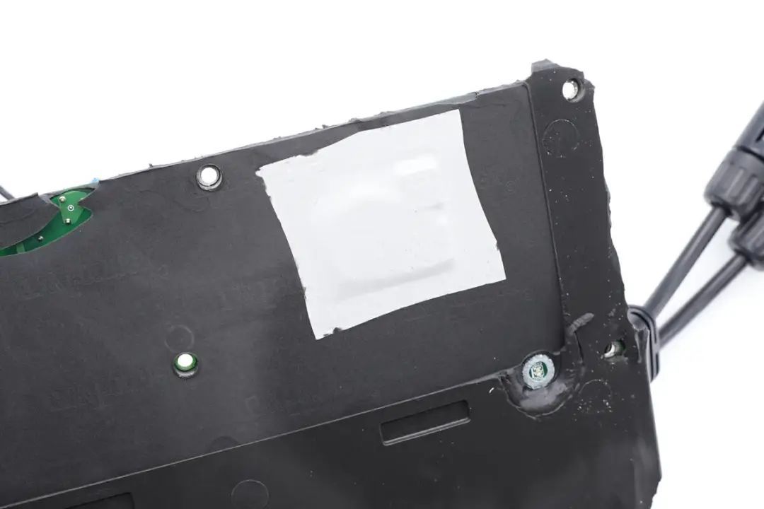
A close-up of the white thermal pad reveals the outline of the internal components.

At the rear of the PCBA module, there is a clear view of the soldered boost switching transistors along with their respective drivers, high-voltage rectifier diodes, and the H-bridge circuit used for modulation.
Soldering of a 3mΩ Resistor for Current Detection on the DC Input Side.
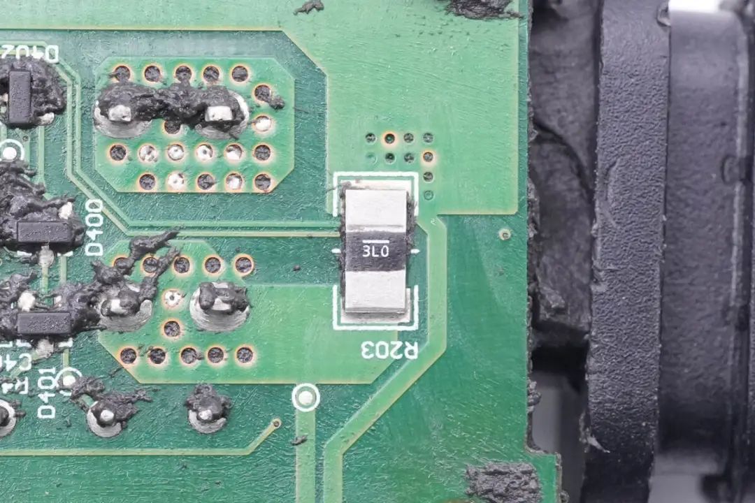
Another 3mΩ sample resistor is similarly soldered on the opposite end.
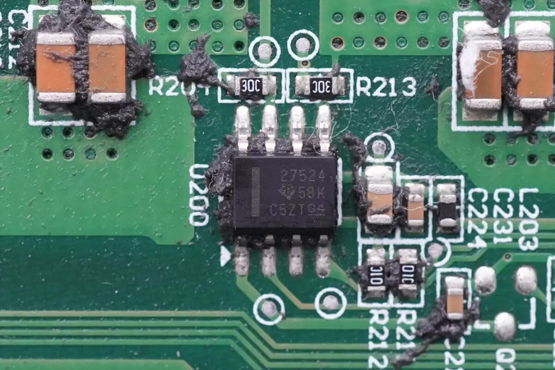
Use of UCC27524 High-Speed Low-Side Gate Drivers from Texas Instruments for Driving Boost MOSFETs.The gate drivers for driving the boost MOSFETs are Texas Instruments' UCC27524. These are dual-channel high-speed low-side gate drivers with a peak drive current of 5A. They support TTL and CMOS signal voltage levels and operate within a voltage range of 4.5-18V.

The boost MOSFETs are from Infineon, bearing the part number BSC190N15NS3-G. These are N-channel MOSFETs with a voltage tolerance of 150V and an on-resistance of 19mΩ. Two of these MOSFETs are connected in parallel, totaling four to correspond to two transformers.
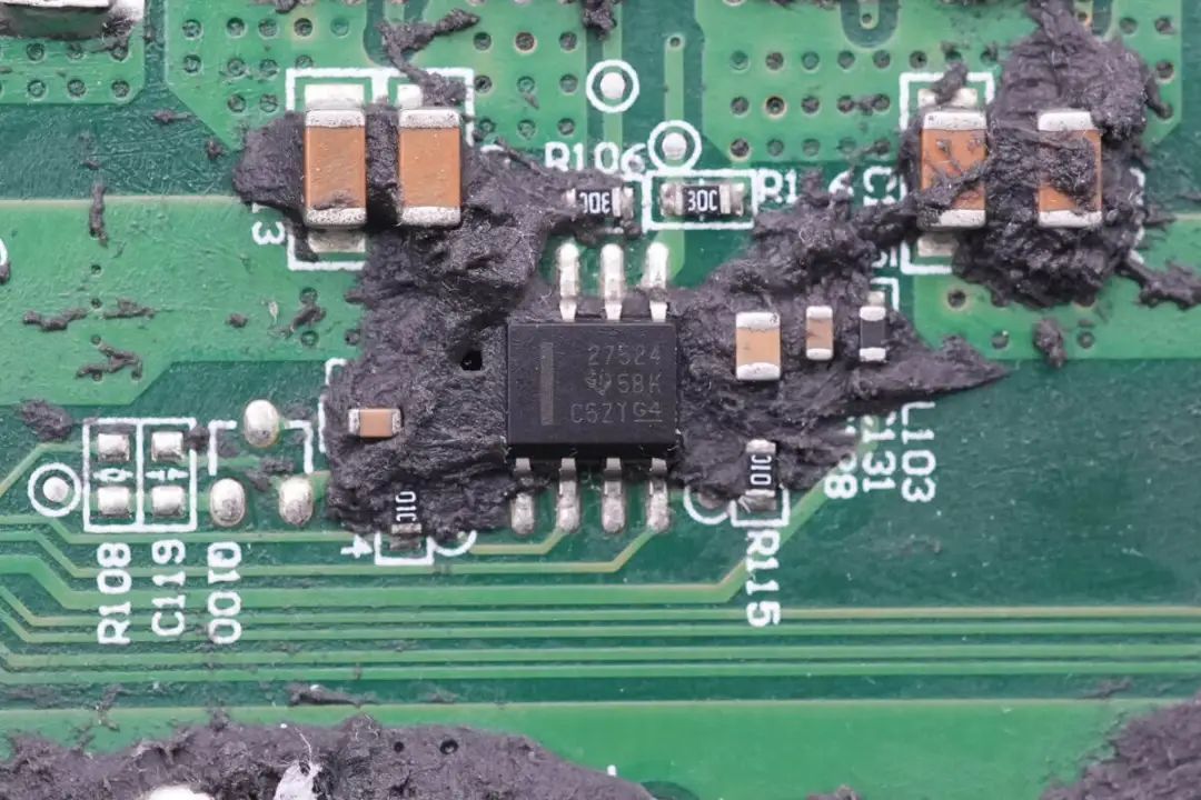
The Other Input Shares the Same Configuration: UCC27524 Drivers and BSC190N15NS3-G MOSFETs.

The other input path has a matching configuration with UCC27524 drivers .

BSC190N15NS3-G MOSFETs.

Three operational amplifiers (op-amps) are featured, all of which are from Micromax Technology. The two on the sides are MCP6002 low-power dual op-amps, while the one in the middle is an MCP6062E high-precision dual op-amp.
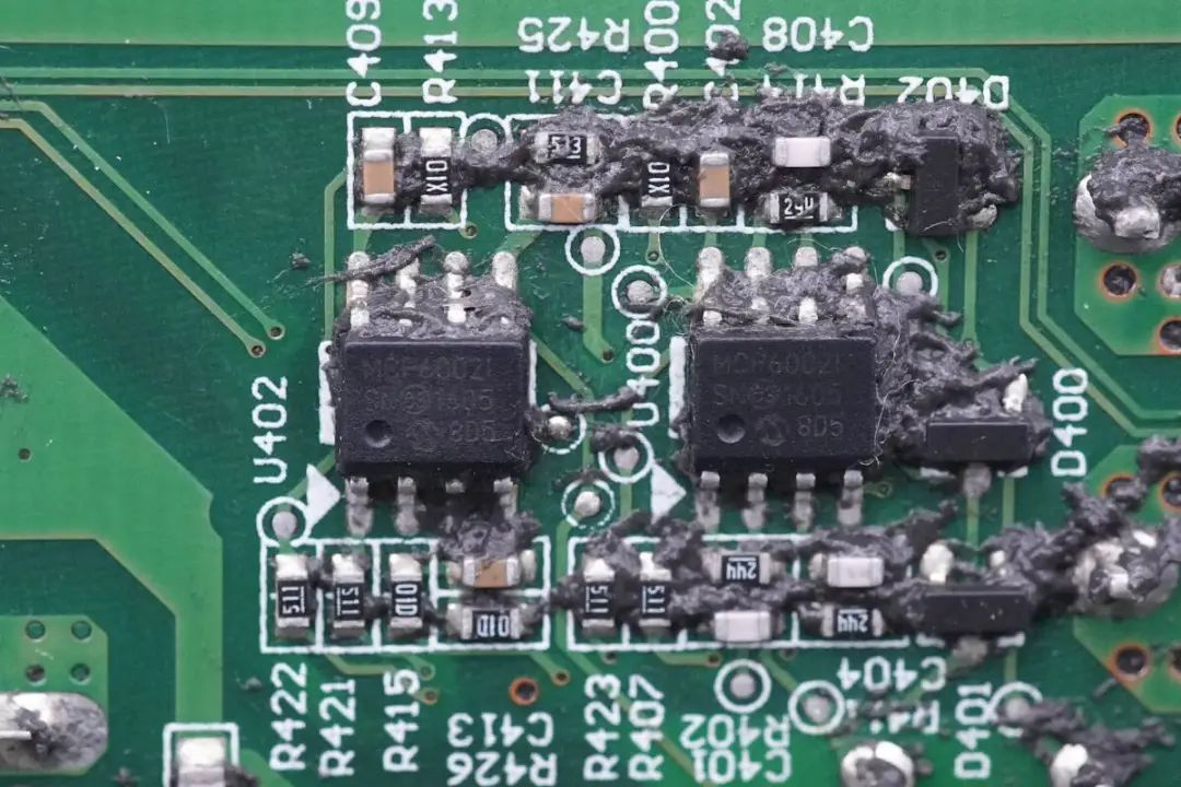
Two more MCP6002 op-amps are soldered on one side of the PCBA.
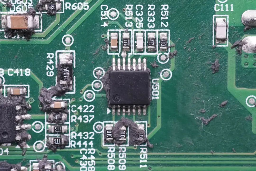
An ON Semiconductor MC74HC14A Hex Inverter with Schmitt Trigger Inputs for Signal Shaping.

High-Voltage Rectifier Diodes for Boost Output from Cree (Part Number C4D02120E).
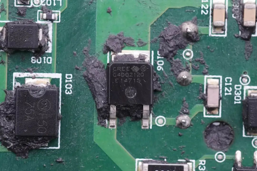
High-voltage rectifier diodes for the boost output come from Cree and bear the part number C4D02120E. These are silicon carbide diodes with a voltage tolerance of 1200V and are in TO252 packages.
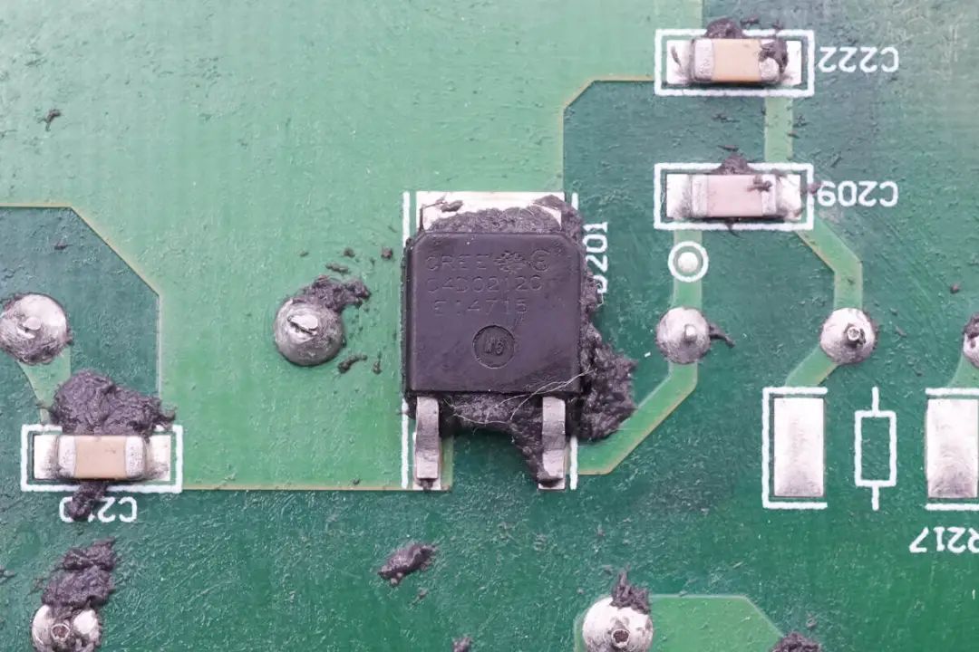
Four Transformers Are Used in Total for Corresponding to Two Sets of Boost Circuits.
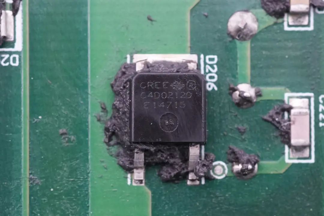
Silicon Carbide Diode from Cree for the Other Set of Boost Circuits.
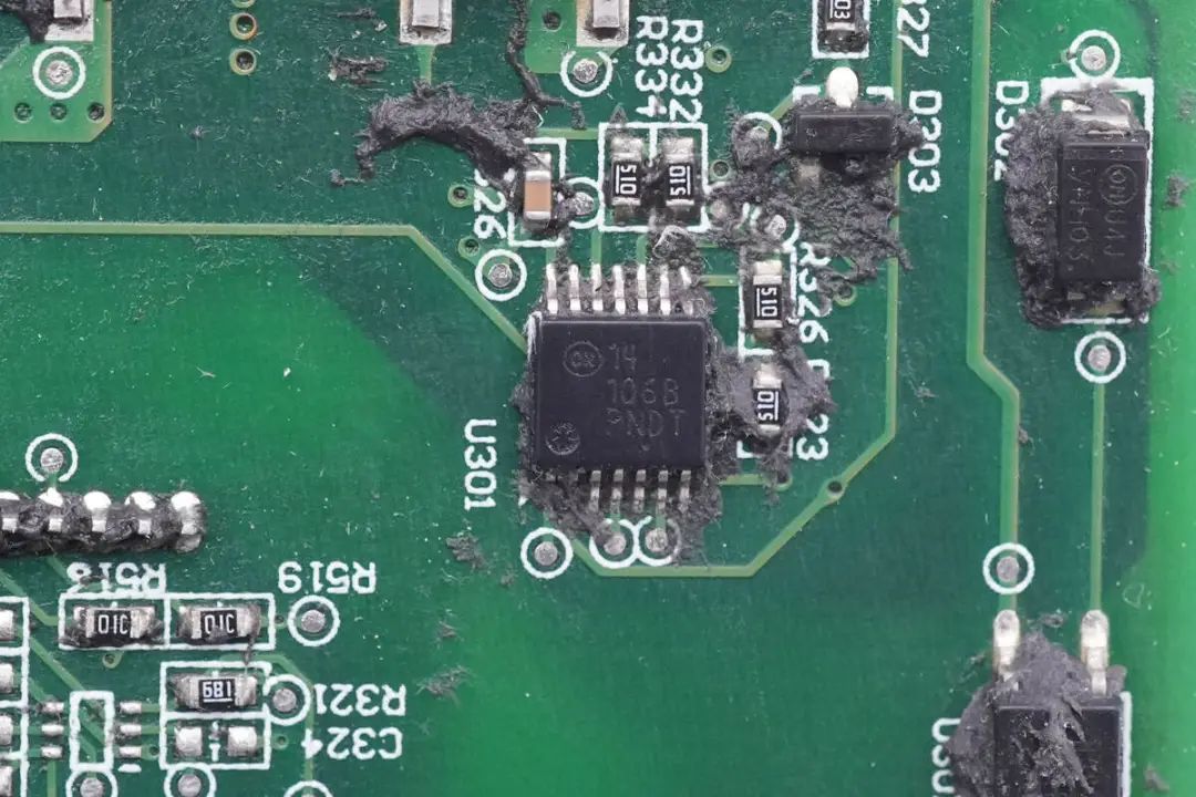
A close-up view of another silicon carbide diode is provided.
Signal Shaping for Output Modulation Uses an ON Semiconductor MC14106B Hex Schmitt Trigger.
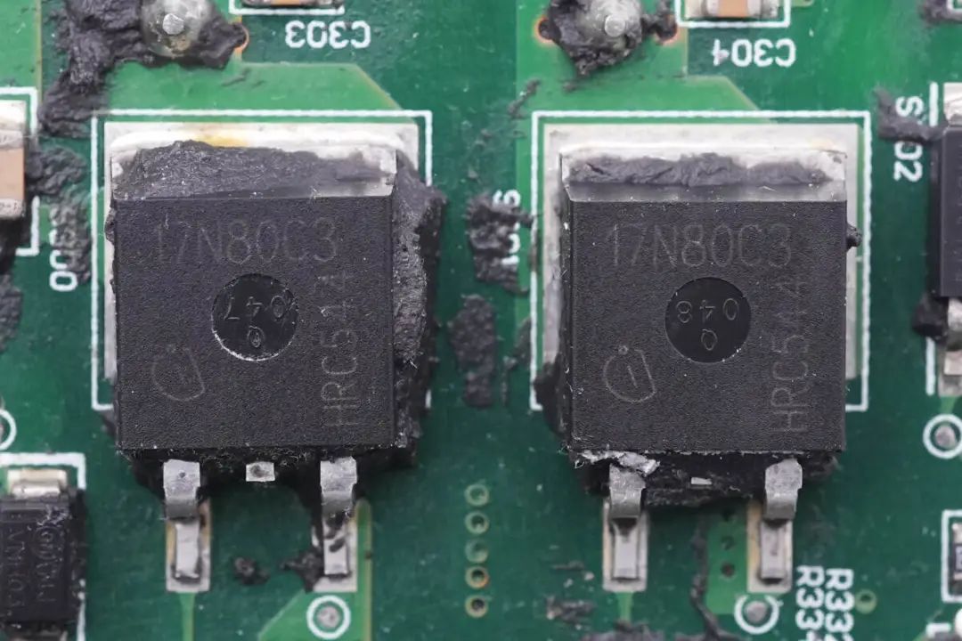
Two N-channel MOSFETs are used from Infineon, bearing the part number SPB17N80C3. These MOSFETs have a voltage tolerance of 800V and an on-resistance of 290mΩ. They are in TO263 packages.
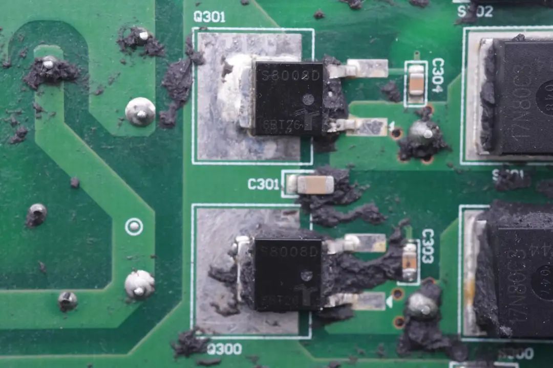
Two controlled rectifiers (SCRs) are used from Littelfuse, bearing the part number S8008D. These SCR modules are rated for 800V voltage tolerance and have an 8A nominal current rating. They are in TO252 packages.
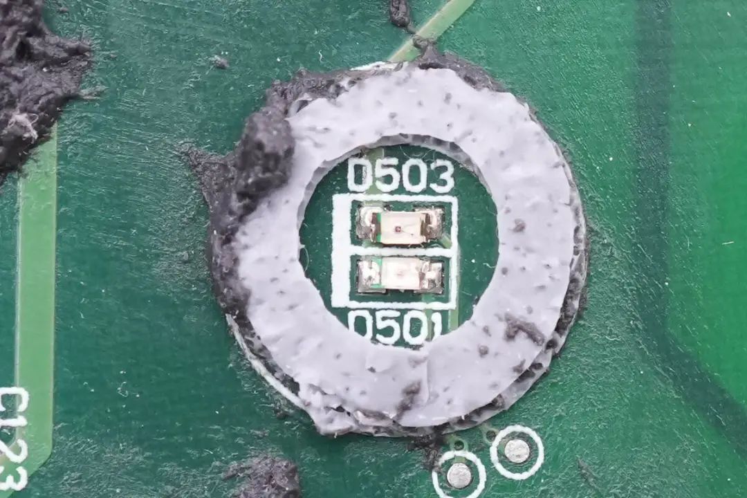
Close-Up of Two Indicator Lights with Rubber Sealing.
with the end of the Disassembly, following with a overview.
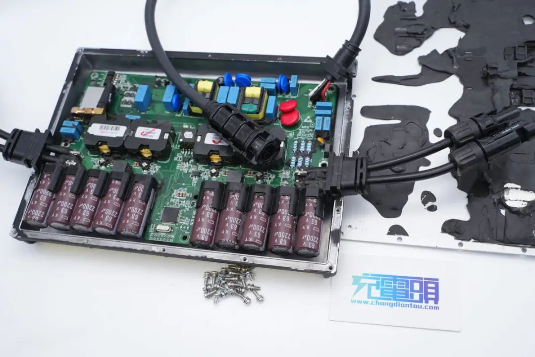
Charging Head Network Disassembly Summary
Hoymiles has introduced a solar microinverter that supports two DC inputs and one AC output, with an AC output power of 700W. It also features a built-in wireless module for inverter communication. The inverter is housed in an all-aluminum alloy casing, securely fastened with screws. This all-aluminum alloy casing enhances the inverter's heat dissipation capabilities, reducing operating temperatures.
Through the disassembly conducted by the Charging Head Network, it was revealed that this inverter is filled with thermal adhesive inside the casing, further enhancing its heat dissipation performance. Internally, it utilizes a TMS320F28035 MCU from Texas Instruments for overall inverter control and employs UCC27524 for driving the boost MOSFETs. The inverter incorporates four transformers corresponding to the two DC input paths, and the boost MOSFETs are sourced from Infineon, specifically the BSC190N15NS3-G model.
The transformer outputs are rectified by four CREE C4D02120 1200V silicon carbide diodes. Modulation signals are transmitted using optocoupler isolation and signal shaping is performed with an ON Semiconductor MC74HC14A. The Infineon SPB17N80C3 transistors and two controlled rectifiers (SCRs) are used for output modulation. Input electrolytic capacitors are from GuiMiGong, while output filtering and protective components are from EPCOS. The inverter utilizes top-tier components and is filled with thermal adhesive to enhance heat dissipation, ensuring its suitability for high-temperature environments.


